5 - 21
5 DriveProgramming User Variables
DriveProgramming User’s Manual (I622-E1)
5-7 Output Variables
5
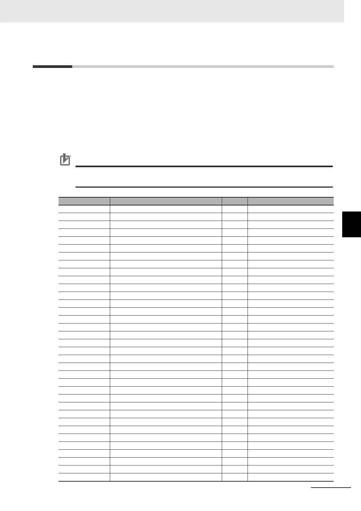
5-7 Output Variables
You can execute the functions which can be allocated to the output terminals by using the DrivePro-
gramming program. The following variables correspond to the functions which can be allocated to the
output terminals.
Setting each variable to 1 (ON) or 0 (OFF) causes the same operation as when the output function
turns the output terminal ON/OFF. You can monitor the status on the program even if you do not set
each function in the parameters Output Terminal Selection (CC-01 to CC-05) or Relay Output (16C, AL)
Function Selection (CC-06, CC-07). The Reference column in the following table shows the function
setting data for the inverter. For details on each function, refer to the High-function General-purpose
Inverter 3G3RX2 Series User's Manual (I620).
Precautions for Correct Use
When the DriveProgramming program is stopped, the status of the output variables is not
retained but updated according to the actual function status.
Function variable Description R/W Reference
no Without allocation R CC-01 to CC-07 = 0
RUN During operation R CC-01 to CC-07 = 1
FA1 When the constant speed is attained R CC-01 to CC-07 = 2
FA2 Equal to or above the set frequency R CC-01 to CC-07 = 3
FA3 Set frequency only R CC-01 to CC-07 = 4
FA4 Equal to or above the set frequency 2 R CC-01 to CC-07 = 5
FA5 Set frequency only 2 R CC-01 to CC-07 = 6
IRDY Operation ready completion R CC-01 to CC-07 = 7
FWR During normal rotation operation R CC-01 to CC-07 = 8
RVR During reverse rotation operation R CC-01 to CC-07 = 9
FREF Frequency command panel R CC-01 to CC-07 = 10
REF Operation command panel R CC-01 to CC-07 = 11
SETM Second control under selection R CC-01 to CC-07 = 12
OPO Optional output R CC-01 to CC-07 = 16
AL Alarm signal R CC-01 to CC-07 = 17
MJA Severe failure signal R CC-01 to CC-07 = 18
OTQ Excessive torque R CC-01 to CC-07 = 19
IP During instantaneous power failure R CC-01 to CC-07 = 20
UV Under insufficient voltage R CC-01 to CC-07 = 21
TRQ During torque limitation R CC-01 to CC-07 = 22
IPS During power failure deceleration R CC-01 to CC-07 = 23
RNT RUN time elapsed R CC-01 to CC-07 = 24
ONT Power ON time elapsed R CC-01 to CC-07 = 25
THM Electronic thermal warning R CC-01 to CC-07 = 26
THC Electronic thermal warning R CC-01 to CC-07 = 27
WAC Capacitor life advance notice R CC-01 to CC-07 = 29
WAF Fan life advance notice R CC-01 to CC-07 = 30
FR Operation command signal R CC-01 to CC-07 = 31
OHF Cooling fin heating advance notice R CC-01 to CC-07 = 32
LOC Low current signal R CC-01 to CC-07 = 33
LOC2 Low current signal 2 R CC-01 to CC-07 = 34
OL Overload advance notice R CC-01 to CC-07 = 35
OL2 Overload advance notice 2 R CC-01 to CC-07 = 36
BRK Brake release R CC-01 to CC-07 = 37
BER Brake abnormality R CC-01 to CC-07 = 38
 Loading...


