191
B7A Interface Unit Section 3-7
• Power Supply on One Side (Common Power Supply)
• Power Supply on Both Sides (Separate Power Supplies)
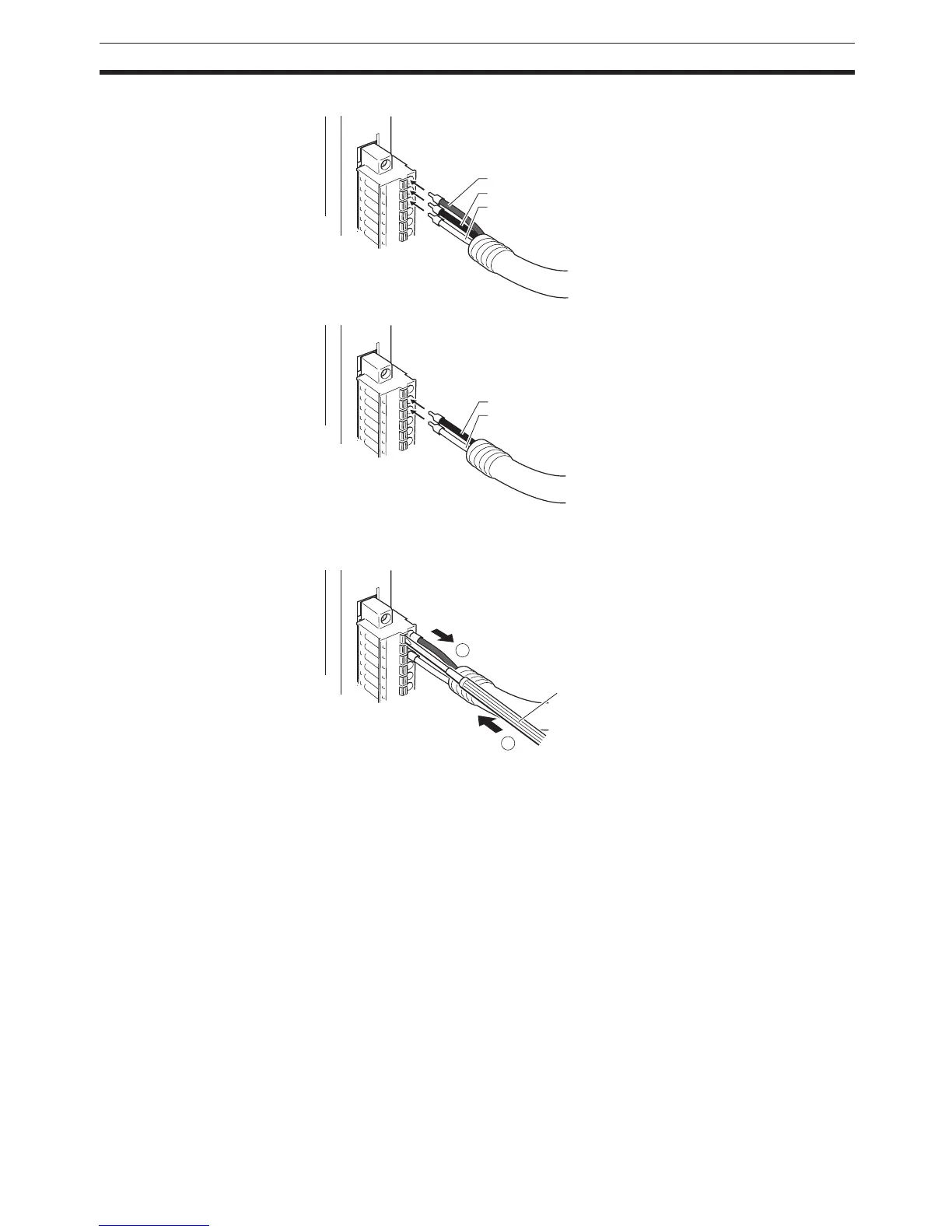
Note To remove the signal lines from the connector, press down on the orange tab
while pulling out the signal line, as shown in the following diagram.
Note To remove the connector from the Unit, fully unscrew the set screws from both
sides of the connector, and then remove the connector.
Forcibly pulling the connector while the set screws are still attached may dam-
age the connector.
3-7-10 Connection Diagrams
Note 1. Confirm that terminals are connected correctly. If connections are incor-
rect, the internal components of the B7A Interface Unit and B7A Link Ter-
minal may be damaged.
2. Route the signal lines in separate ducts both inside and outside the control
panel to isolate them from power lines.
3. Connect cables at a distance that is within the range given in the specifi-
cations.
4. Always turn OFF the power to the CPU Unit and all other Units before con-
necting the communications cables.
5. Always lay communications cables within ducts.
V1
SIG1
G1
SIG1
G1
1
2
Small, flat-
blade screwdriver
 Loading...


