256
Wiring Section 5-3
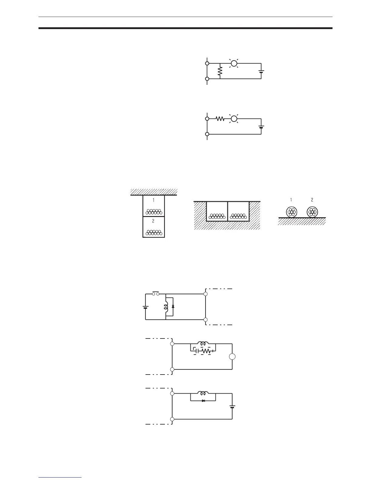
Method 1
Add a resistor that draws about 1/3 of the current consumed by the bulb.
Method 2
Add a control resistor as shown in the following diagram.
5-3-5 Reducing Electrical Noise
I/O Signal Wiring Whenever possible, place I/O signal lines and power lines in separate ducts or
raceways both inside and outside of the control panel.
If the I/O wiring and power wiring must be routed in the same duct, use
shielded cable and connect the shield to the GR terminal to reduce noise.
Inductive Loads When an inductive load is connected to an I/O Unit, connect a surge suppres-
sor or diode in parallel with the load as shown below.
OUT
COM
L
R
+
L
OUT
COM
+
R
1 = I/O cables
2 = Power cables
Suspended duct
In-floor duct
Conduits
L
IN
COM
OUT
COM
OUT
COM
L
L
+
Diode
DC input
Surge suppressor
Diode
Relay output or
transistor output
Relay output or
triac output
 Loading...


