236
Installation Section 5-2
Note 1. When using an I/O Connecting Cable with a locking connector, be sure that
the connector is firmly locked in place before using it.
2. Always turn OFF the power supply to the PLC before connecting a cable.
3. Do not route the I/O Connecting Cables through ducts that contain the I/O
or power wiring.
4. An I/O bus error will occur and the PLC will stop if an I/O Connecting Ca-
ble’s connector separates from the Rack. Be sure that the connectors are
secure.
5. A 63-mm hole will be required if the I/O Connecting Cable must pass
through a hole when connecting an Expansion Rack.
6. The cables can withstand a pulling force up to 49 N (11 lbs), so be sure
that they aren’t pulled too forcefully.
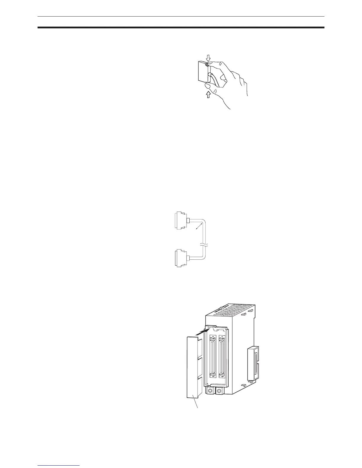
7. The I/O Connecting Cables mustn’t be bent too severely. The minimum
bending radii are shown in the following diagram.
8. Always attach the cover to the output connector (left side) on the last I/O
Interface Unit on the last Expansion Rack to protect it from dust.
R
R = 69 min.
Cable outer diameter: 8.6 mm
OUT
IN
II101
CJ1W-II101
I/O Interface Unit
Out
ut connector cover
 Loading...


