4 Basic Operation
4 - 8
E5@C Digital Temperature Controllers User’s Manual (H174)
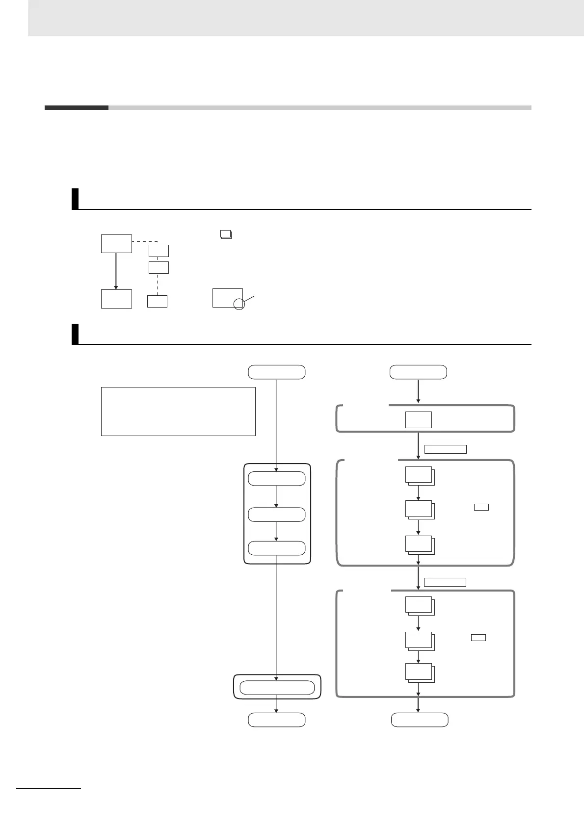
4-2 Initial Setting Examples
Initial hardware setup, including the sensor input type, alarm types, control periods, and other settings,
is done using parameter displays. The O and M Keys are used to switch between parameters, and the
amount of time that you press the keys determines which parameter you move to.
This section describes three typical examples.
* If the Controller is equipped with HB/HS alarm detection, the default setting for the Auxiliary Output 1
Assignment is for heater alarms. Therefore, the alarm 1 function is disabled and the Alarm 1 Type is not
displayed. To enable alarm 1, set an output assignment to alarm 1. For details, refer to 4-6-3 Assigned
Output Functions (Assigning Control Outputs Is Not Supported for Position-proportional Models.).
Explanation of Examples
Example 1
0
in-t
onof
intl
100
in-h
0
in-l
onof
intl
0
25
M
M
M
Changing Parameters
A image means that there are parameters.
Continue pressing the M Key to change parameters
until you reach the intended parameter.
Changing Numbers
Numeric data and selections in each
screen can be changed by using the
U and D Keys.
0
25
M
M
M
M
M
M
Initial Setting Level
Operation Level
5
in-t
onof
cntl
2
alt1
100
25
run
r-5
20
al-1
100
20
onof
pid
run
stop
Input type:
5 (K thermocouple, −200°C to 1,300°C)
Control method: ON/OFF control
Alarm type: 2 (upper limit)
Alarm value 1: 20°C (deviation)
Set point: 100°C
Setup Procedure
Power ON
Set input
specifications
Set control
specifications
Set alarm type
Set SP and alarm values
Start operation
Power ON
Operation Level
PV/SP
Press the O Key for at least 3 s.
Control stops.
Initial Setting Level
Input Type: 5
Check that
control method is
ON/OFF control.
ON/OFF
control:
PID control:
Check alarm type.
Check input type.
Alarm 1 Type*: 2
Press the O Key for at least 1 s.
Control starts.
Operation Level
Use the U and
D Keys to set the
SP to 100°C.
PV/SP:
Confirm that
control is running.
Running
Stopped:
Use the U and
D Keys to set the
alarm value to
20°C.
Alarm Value 1:
Start operation.
An s.err error will be
displayed if the power
supply is turned ON before
the sensor is connected.

 Loading...


