2 Preparations
2 - 36
E5@C Digital Temperature Controllers User’s Manual (H174)
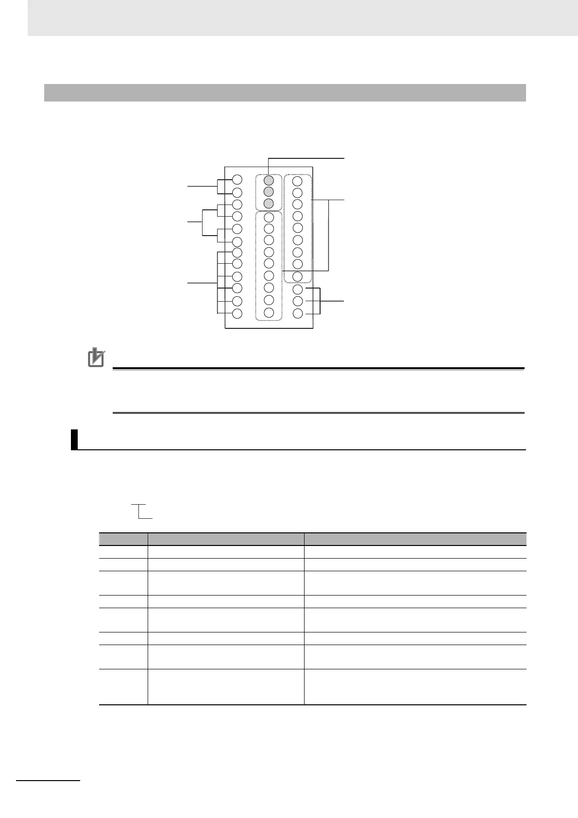
Terminal Arrangement
The terminals block is divided into five types of terminals: control outputs 1 and 2, sensor input, auxiliary
outputs, input power supply, and options.
Precautions for Correct Use
• When you purchase the Digital Controller, it will be set for a K thermocouple (input type = 5). If
a different sensor is used, an input error (s.err) will occur. Check the setting of the Input Type
parameter.
Model Numbers
The specifications for control outputs 1 and 2 are given in the following location in the model number.
2-2-4 E5EC/E5AC Terminal Block Wiring Example
Control Outputs 1 and 2
Code Output type Specification
RX 1 relay output 250 VAC, 5 A (resistive load)
QX 1 voltage output (for driving SSR) 12 VDC, 40 mA
CX 1 linear current output 4 to 20 mA DC or 0 to 20 mA DC with load of 500 Ω
max.
QQ 2 voltage outputs (for driving SSRs) 12 VDC, 21 mA
QR 1 voltage output (for driving SSR) and
1 relay output
12 VDC, 21 mA for voltage output
250 VAC, 5 A (resistive load) for relay output
RR or PR 2 relay outputs 250 VAC, 5 A (resistive load)
CC 2 linear current outputs 4 to 20 mA DC or 0 to 20 mA DC with load of 500 Ω
max.
CQ 1 linear current output and 1 voltage
output (for driving SSRs)
4 to 20 mA DC or 0 to 20 mA DC with load of 500 Ω
max. for current output and 12 VDC, 21 mA for voltage
output
Input Power Supply
Control outputs 1 and 2
Auxiliary Outputs
Sensor input
Options
Not used.
1
31
25
2
3
4
5
6
12
11
7
9
8
10
26
27
32
33
34
35
36
30
29
28
16
17
18
13
14
15
22
23
24
19
20
21
E5@C-@@ @ @ @ M-@@@
Control outputs 1 and 2

 Loading...


