1 Introduction
1 - 6
E5@C Digital Temperature Controllers User’s Manual (H174)
E5CC (Models with Screw Terminal Blocks)
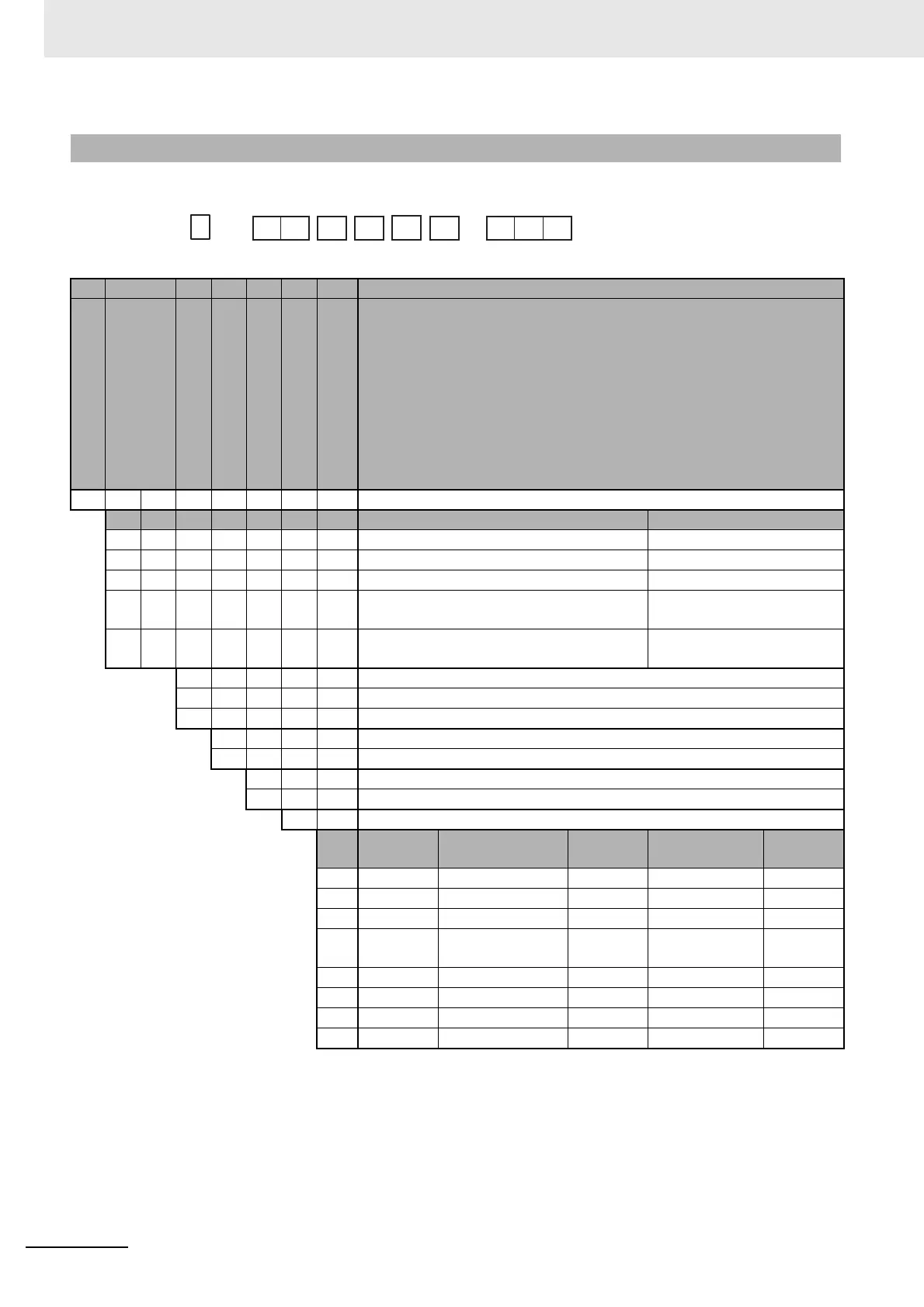
*1 Options with HB and HS alarms (001, 002, and 003) cannot be selected if a linear current output is selected for the
control output.
The control output cannot be used as a simple transfer output.
*2 If no auxiliary outputs (none) is selected, 000 (none) must be selected for the options.
*3 These cannot be selected if 5 (screw terminals with cover) is selected for the terminal type.
1-2-2 Model Number Legends
(1) (2) (3) (4) (5) (6) (7) Meaning
C 48 × 48 mm
Control output 1 Control output 2
R X Relay output None
Q X Voltage output (for driving SSR) None
*1 C X Linear current output None
Q Q Voltage output (for driving SSR) Voltage output
(for driving SSR)
C Q Linear current output Voltage output
(for driving SSR)
*2*3 0 None
*3 2 2
33
A 100 to 240 VAC
D 24 VAC/DC
S Screw terminals
5 Screw terminals (with cover)
M Universal input
Event
inputs
Communications
Remote
SP Input
HB alarm and
HS alarm
Transfer
output
000 --- --- --- --- ---
001 2 --- --- 1 ---
*3 002 --- RS-485 --- 1 ---
003 --- RS-485 --- 2 (for 3-phase
heaters)
---
004 2 RS-485 --- --- ---
005 4 --- --- --- ---
006 2 --- --- --- Provided.
007 2 --- Provided. --- ---
--
-
E5CC
-
-
(1) (2) (3) (4) (5) (6) (7)

 Loading...


