4 Basic Operation
4 - 32
E5@C Digital Temperature Controllers User’s Manual (H174)
4-10 Alarm Outputs
• Alarms are output from auxiliary outputs. For relay outputs or voltage outputs (for driving SSRs),
alarms can also be used by setting the Control Output 1 Assignment or Control Output 2 Assignment
parameter to any of the alarms from alarm 1 to 4. The alarm output condition is determined by a
combination of the alarm type, alarm value, alarm hysteresis, and the standby sequence. For details,
refer to 4-11 Alarm Hysteresis.
• This section describes the Alarm Type, Alarm Value, Upper-limit Alarm and Lower-limit Alarm
parameters.
4-10-1 Alarm Types
• Set the alarm type independently for each alarm in the Alarm 1 to 4 Type
parameters in the Initial Setting Level.
• The alarms that can be set are listed in the following table.
• You can use an LBA (12) only for alarm 1. You cannot use an LBA on a
Position-proportional Model.
• If the Controller is equipped with HB/HS alarm detection, the default setting for
the Auxiliary Output 1 Assignment is for heater alarms. Therefore, the alarm 1
function is disabled and the Alarm 1 Type is not displayed. To use alarm 1, set
an output assignment to alarm 1. (Refer to 4-6-3 Assigned Output Functions
(Assigning Control Outputs Is Not Supported for Position-proportional
Models.).)
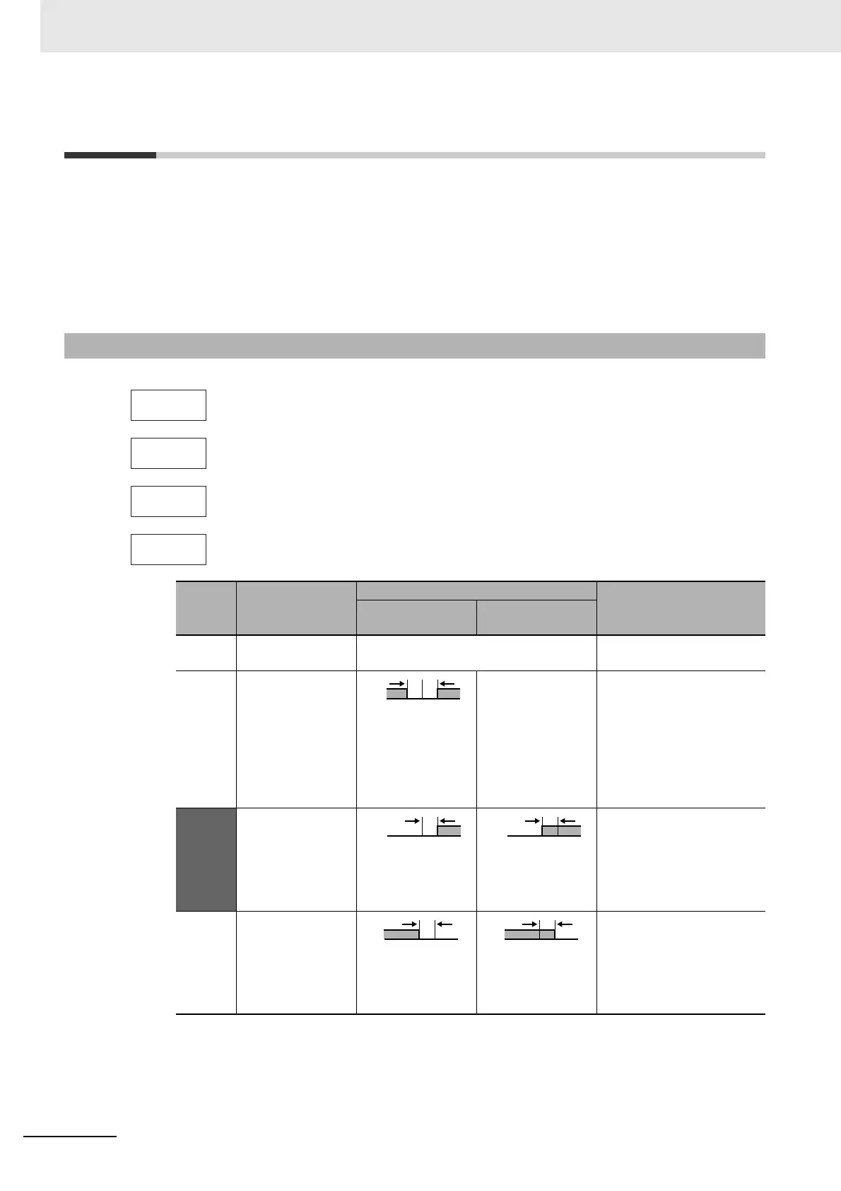
Set
value
Alarm type
Alarm output operation
Description of function
When alarm value
X is positive
When alarm value
X is negative
0 Alarm function
OFF
Output OFF No alarm
1 Upper- and
lower-limit*1
*2 Set the upward deviation in
the set point for the alarm
upper limit (H) and the
lower deviation in the set
point for the alarm lower
limit (L). The alarm is ON
when the PV is outside this
deviation range.
2
(default)
Upper-limit Set the upward deviation in
the set point by setting the
alarm value (X). The alarm
is ON when the PV is higher
than the SP by the deviation
or more.
3 Lower-limit Set the downward deviation
in the set point by setting
the alarm value (X). The
alarm is ON when the PV is
lower than the SP by the
deviation or more.
alt2
alt3
alt4
Alarm 4 Type
ON
OFF PV
LH
SP

 Loading...


