4 Basic Operation
4 - 44
E5@C Digital Temperature Controllers User’s Manual (H174)
• If there is little difference between the current in normal and abnormal states, detection may be
unstable. To stabilize detection, set a current difference of at least 1.0 A for heaters lower than
10.0 A, and at least 2.5 A for heaters of 10.0 A or higher. If the heater current is too low, loop the
load line several times through a CT, as shown in the following diagram. Looping it through once
will double the detected current.
Precautions for Correct Use
Due to UL Listing requirements, use the E54-CT1L or E54-CT3L Current Transformer with the
factory wiring (internal wiring). Use a UL category XOBA or XOBA7 current transformer that is
UL Listed for field wiring (external wiring) and not the factory wiring (internal wiring).
• CTs can be used for the heater burnout (HB) and heater short (HS) alarms.
For the E5CC, connect the CT in advance to terminals 16 and 17 (CT1), or 17 and 18 (CT2). For the
E5CC-B, connect the CT in advance to terminals 21 and 22 (CT1). For the E5EC or E5AC, connect
the CT in advance to terminals 19 and 20 (CT1) or 20 and 21 (CT2). For the E5EC-B, connect the CT
in advance to terminals 25 and 26 (CT1). For the E5DC, E5DC-B or E5GC, connect the CT in
advance to terminals 7 and 8 (CT1). Then pass the heater power line through the hole in the CT. For
specifications, models, and dimensions of the CTs that can be used with the Digital Controller, refer
to A-2 Current Transformer (CT).
(1) Single-phase Heaters
For single-phase heaters, install the CT in the position shown in the following diagram.
(2) Three-phase Heaters
When a 3-phase power supply is used, regardless of the types of connecting lines, two
current transformers (CTs) are required to detect heater burnouts and heater shorts.
• Setting the Leakage Current Value Monitor
1
Press the M Key several times in the Adjustment Level to dis-
play lcr1 (Leakage Current 1 Value Monitor).
Adjustment Level
2
Check the leakage current from the CT input that is used to
detect heater short.
The monitoring range is 0.0 to 55.0 A.
• Setting Heater Short Alarm Detection
1
Press the M Key several times in the Adjustment Level to dis-
play hs1 (HS Alarm 1).
Adjustment Level
2
Press the U or D Key to set the set value to 2.5
Refer to 4-12-4 Calculating Detection Current Values when you set
the value.
4-12-3 Installing Current Transformers (CT)
0.0
lcr1
Leakage Current 1
Value Monitor
HS Alarm 1
50.0
hs1
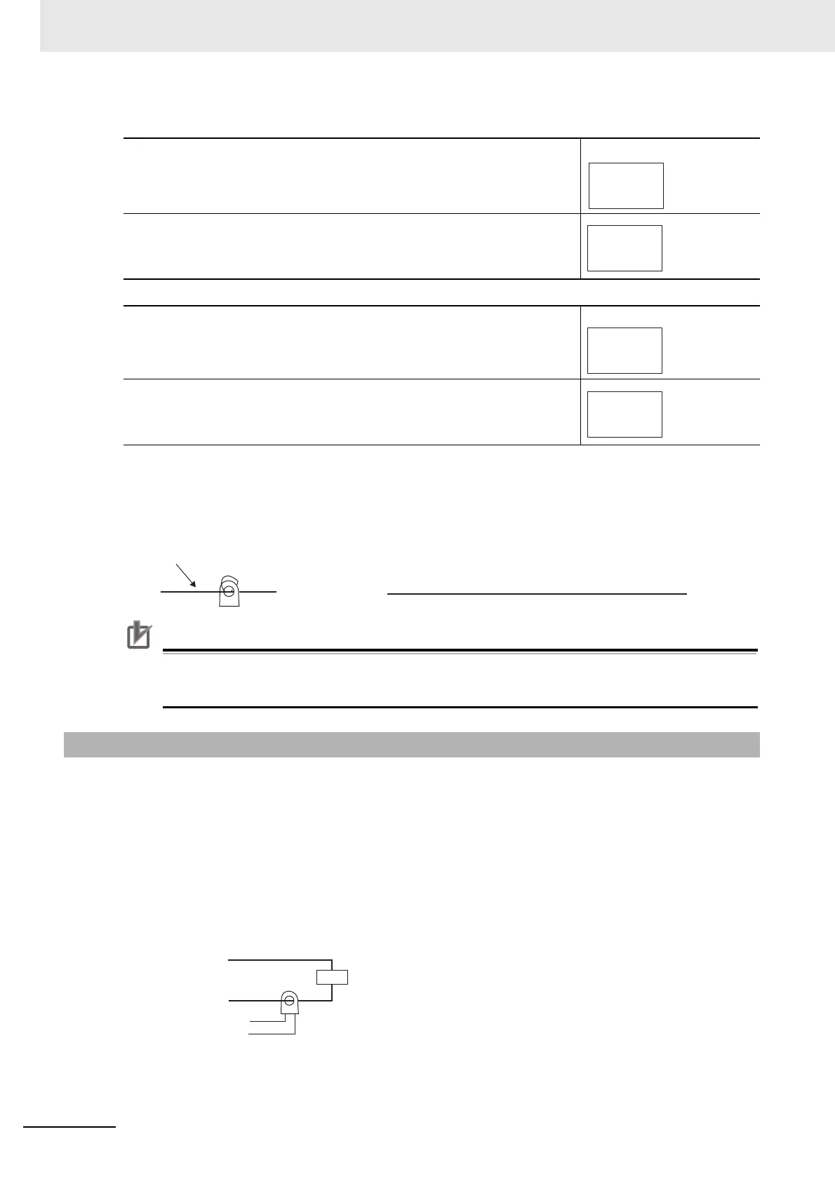
CT
Load line
HS Alarm 1/2 set value =
(Leakage current value (output OFF) + HS current value) × Number of turns
2
CT
Load
Load (such as a heater)
AC line
Product
To CT input

 Loading...


