5 Advanced Operations
5 - 26
E5@C Digital Temperature Controllers User’s Manual (H174)
5-10 Alarm Delays
• Delays can be set for the alarm outputs. ON and OFF delays can be set separately for alarms 1, 2, 3,
and 4. The ON and OFF delays for alarms 1, 2, 3, and 4 also apply to the individual SUB1, SUB2,
SUB3, and SUB4 indicators and to communications status. The alarm ON delays will also function
when power is turned ON or when moving from the Initial Setting Level to Operation Level (e.g., to
software resets). All outputs will turn OFF and the OFF delays will not function when moving to the
Initial Setting Level or when an alarm is output for an A/D converter error.
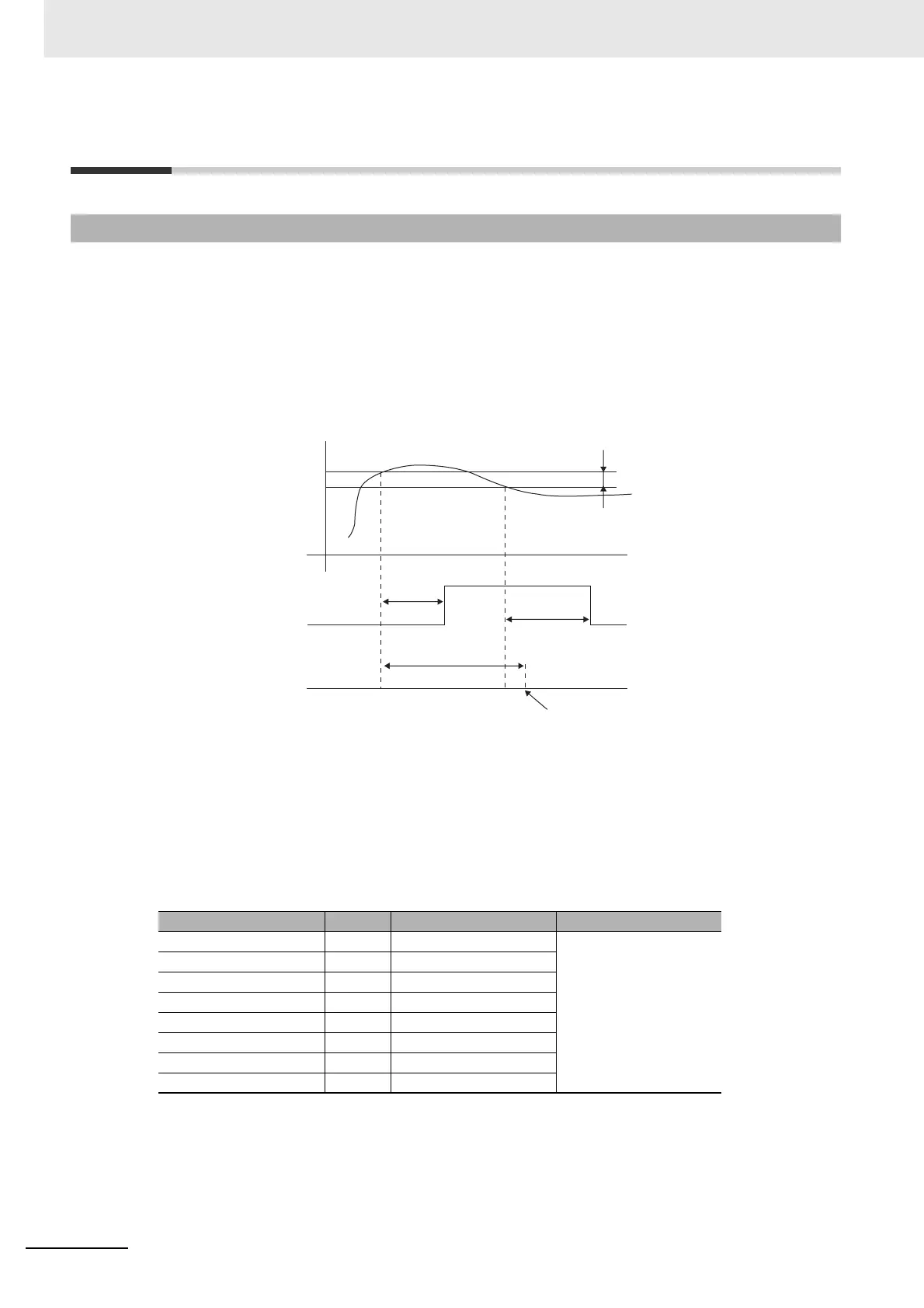
Operation of Alarm ON and OFF Delays (for an Upper-limit Alarm)
• The alarm will not turn ON if the time that the alarm is ON is equal to or less than the ON delay set
time. Also, the alarm will not turn OFF if the time that the alarm is OFF is equal to or less than the
OFF delay set time.
• If an alarm turns OFF and then back ON during the ON delay time, the time will be remeasured
from the last time the alarm turns ON. Also, if an alarm turns ON and then back OFF during the
OFF delay time, the time will be remeasured from the last time the alarm turns OFF.
Parameters Related to Alarm Delays
Note1: The defaults are 0, i.e., the ON and OFF delays are disabled.
2: The parameters are displayed when alarm functions are assigned and when the alarm type is set to
any type but 0 (none), 12: LBA, or 13: PV change rate alarm.
5-10-1 Alarm Delays
Parameter name Display Set (monitor) values Level
Alarm 1 ON Delay a1on 0 to 999 (s)
Advanced Function
Setting Level
Alarm 2 ON Delay a2on 0 to 999 (s)
Alarm 3 ON Delay a3on 0 to 999 (s)
Alarm 4 ON Delay a4on 0 to 999 (s)
Alarm 1 OFF Delay a1of 0 to 999 (s)
Alarm 2 OFF Delay a2of 0 to 999 (s)
Alarm 3 OFF Delay a3of 0 to 999 (s)
Alarm 4 OFF Delay a4of 0 to 999 (s)
PV
Alarm setting
Alarm hysteresis
Alarm status
ON delay set
time
ON delay set time
OFF delay set
time
Alarm Latch = OFF
Alarm will not turn ON.

 Loading...


