2 - 41
2 Preparations
E5@C Digital Temperature Controllers User’s Manual (H174)
2-2 Using the Terminals
2
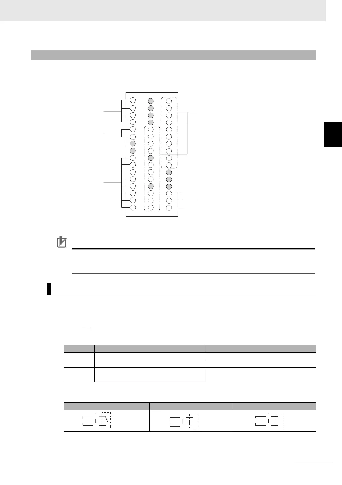
2-2-5 E5EC-B Terminal Block Wiring Example
Terminal Arrangement
The terminals block is divided into five types of terminals: control output 1, sensor input, auxiliary outputs, input
power supply, and options.
Note: The terminals that are shaded gray are not used.
Precautions for Correct Use
When you purchase the Digital Controller, it will be set for a K thermocouple (input type = 5). If a
different sensor is used, an input error (s.err) will occur. Check the setting of the Input Type
parameter.
Model Numbers
The specification for control output 1 is given in the following location in the model number.
Terminal Details
2-2-5 E5EC-B Terminal Block Wiring Example
Control Output 1
Code Output type Specification
RX 1 relay output 250 VAC, 5 A (resistive load)
QX 1 voltage output (for driving SSR) 12 VDC, 40 mA
CX 1 linear current output 4 to 20 mA DC or 0 to 20 mA DC with load of
500 Ω max.
RX QX CX
Input power supply
Control output 1
Auxiliary outputs
Sensor input
Options
41
10
11
12
13
14
15
16
17
18
19
45
29
28
27
41
36
35
34
33
46
44
43
42
40
39
38
37
20
21
22
23
24
25
26
47
48
32
31
30
1
2
3
4
6
9
7
8
5
E5EC-@@ @ @ B M-@@@
Control output 1
E
F
Relay output
Control output 1
+
−
E
F
Voltage output
(for driving SSR)
Control output 1
E
F
+
−
Control output 1
Linear current
output

 Loading...


