2 Preparations
2 - 42
E5@C Digital Temperature Controllers User’s Manual (H174)
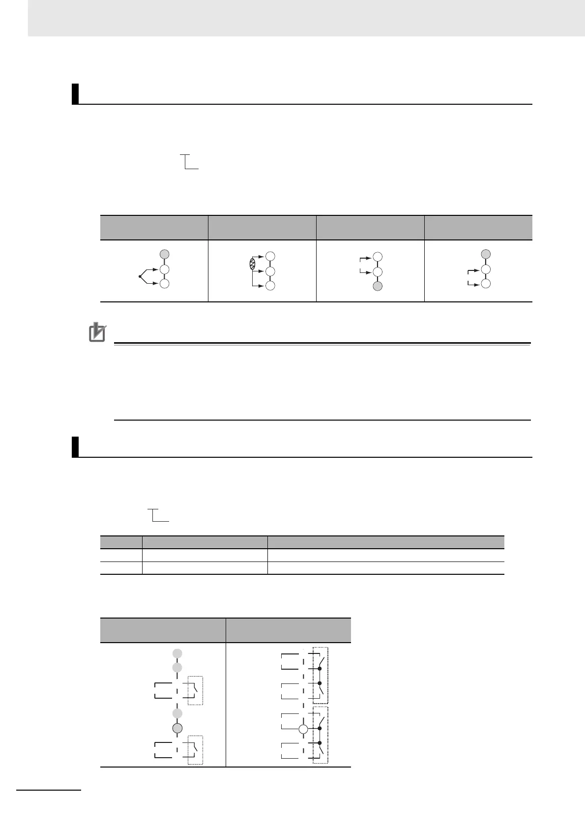
Model Numbers
All models have universal sensor inputs, so the code in the model number is always “M.”
Terminal Details
Do not connect anything to the terminals that are shaded gray.
Precautions for Correct Use
• When complying with EMC standards, the line connecting the sensor must be 30 m or less. If
the cable length exceeds 30 m, compliance with EMC standards will not be possible.
• The sensor input is not electrically isolated from the internal circuits. If you use a grounded
thermocouple, do not connect one of the sensor input terminals to ground. (If the sensor input
terminals are connected to ground, errors will occur in the measured temperature as a result
of leakage current.)
Model Numbers
The number of auxiliary outputs is given in the following location in the model number.
Terminal Details
Do not connect anything to the terminals that are shaded gray.
* Common terminals are indicated with asterisks (*).
Sensor Input
TC (thermocouple)
Pt (resistance
thermometer)
I (current) V (voltage)
Auxiliary Outputs
Code Auxiliary outputs Specification
2 Model with 2 auxiliary outputs SPST-NO, 250 VAC, 3 A
4 Model with 4 auxiliary outputs SPST-NO, 250 VAC, 2 A
Model with 2 auxiliary
outputs
Model with 4 auxiliary
outputs
E5EC-@@ @ @ S M-@@@
Sensor input
A
B
B
30
31
32
+
−
V
30
31
32
E5EC-@@ @ @ S M-@@@
No. of auxiliary outputs
J
Auxiliary output 1
Auxiliary output 2
O
P
I
M
K
L
14
I
K
J
L
*
Auxiliary output 4
Auxiliary output 3
M
O
P
*
Auxiliary output 2
Auxiliary output 1
14