7 - 9
7 User Calibration
E5@C Digital Temperature Controllers User’s Manual (H174)
7-5 Calibrating Analog Input
7
7-5 Calibrating Analog Input
Calibrating a Current Input
In this example, calibration is shown for a Digital Controller with an analog input, with a current input
set as the input type.
1. Connect the power supply.
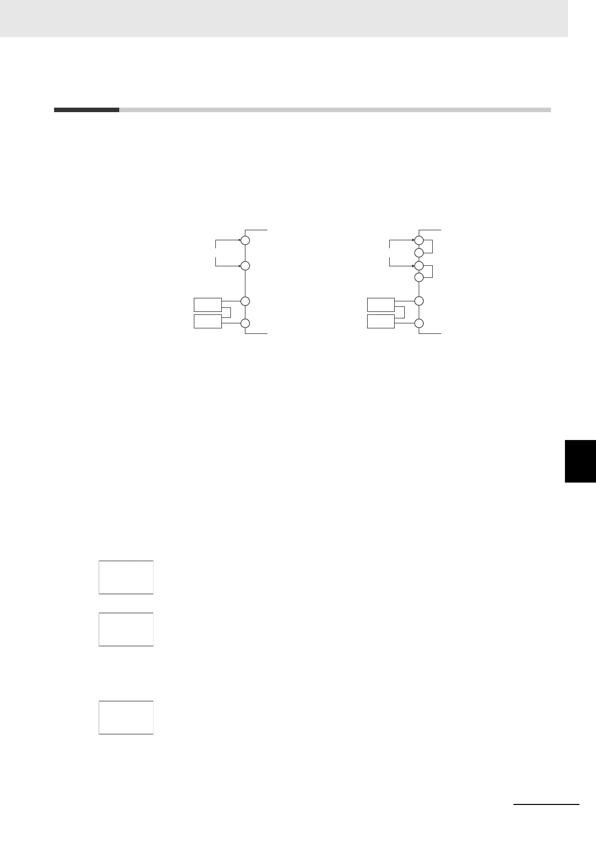
2. Connect an STV and DMM to the current input terminals, as shown in the following diagram.
3. Turn the power ON.
4. Move to the Calibration Level.
This starts the 30-minute aging timer. This timer provides an approximate timer for aging.
After 30 minutes have elapsed, the No. 2 display changes to 0. You can advance to the next
step in this procedure even if 0 is not displayed.
5. When the M Key is pressed, the status changes as shown to the left.
The No. 2 display at this time shows the currently entered count value in hexadecimal. Set the
STV to 20 mA.
Allow the count value on the No. 2 display to fully stabilize, then press the D Key to
temporarily register the calibration settings.
If this count value is outside of the specified range, the No. 2 display will flash and the count
value will not be temporarily registered.
6. When the M Key is pressed, the status changes as shown to the left.
Set the STV to 1 mA.
Allow the count value on the No. 2 display to fully stabilize, then press the D Key to
temporarily register the calibration settings.
If this count value is outside of the specified range, the No. 2 display will flash and the count
value will not be temporarily registered.
Input power supply
Input power supply
E5CC/E5CC-U/E5EC/E5AC/E5DC/E5DC-B/E5GC
+
−
C
C'
D
D'
E5CC-B/E5EC-B
−
+
*
*
* Common terminals are indicated with asterisks (*).
STV
DMM
C
D
STV
DMM
The terminal numbers are as follows:
• Input Terminals (Negative and Positive)
E5CC: 5 and 4
E5CC-U: 2 and 3
E5EC/E5AC: 23 and 22
E5DC: 13 and 12
E5DC-B: 11 and 15
E5GC: 11 and 10
• Input Power Supply (C/D)
E5CC: 11 and 12
E5CC-U: 10 and 11
E5EC/E5AC: 1 and 2
E5DC: 1 and 2
E5DC-B: 1 and 2
E5GC: 1 and 2
The terminal numbers are as follows:
• Input Terminals (Negative and Positive)
E5CC-B: 7 and 6
E5EC-B: 31 and 30
• Input Power Supply (C or C', and D or D')
E5CC-B: 13 or 14, and 15 or 16
E5EC-B: 1 or 2, and 3 or 4

 Loading...


