A-17
Appendices
NJ-series CPU Unit Hardware User’s Manual (W500)
A-2 Specifications of Basic I/O Units
A
A-2-2 Basic I/O Units
CJ1W-INT01 Interrupt Input Unit (16 Points)
* Terminal numbers A0 to A8 and B0 to B8 are used in the external connection and terminal-device variable diagrams. They are not printed
on the Units.
Note Interrupt Input Units can be used as normal Basic I/O Units. They cannot be used to start I/O interrupt tasks.
Name 16-point Interrupt Input Unit with Terminal Block
Model CJ1W-INT01
Rated Input Voltage 24 VDC
Allowable Input Voltage Range 20.4 to 26.4 VDC
Input Impedance 3.3 k
Input Current 7 mA typical (at 24 VDC)
ON Voltage/ON Current 14.4 VDC min./3 mA min.
OFF Voltage/OFF Current 5 VDC max./1 mA max.
ON Response Time 0.05 ms max.
OFF Response Time 0.5 ms max.
Number of Circuits 16 (16 points/common, 1 circuit)
Number of Simultaneously ON Points 100% (16 points/common) simultaneously ON (24 VDC)
Insulation Resistance 20 M between external terminals and GR terminal (at 100 VDC)
Dielectric Strength
1,000 VAC between external terminals and GR terminal for 1 minute at a leakage current of 10 mA
max.
Internal Current Consumption 80 mA max.
Weight 110 g max.
Accessories None
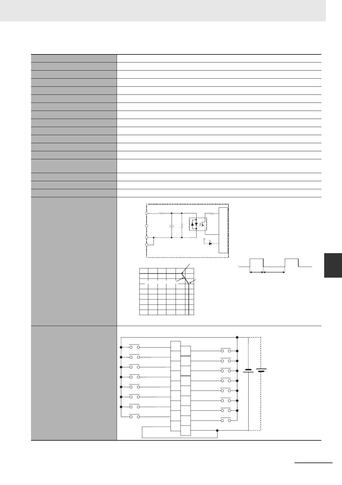
Circuit Configuration
• Up to two Interrupt Input Units can be
mounted to the CPU Rack. They must
be connected as one of the five Units
immediately next to the CPU Unit. If an
Interrupt Input Unit is connected in any
other position, an Incorrect Unit/Expan-
sion Rack Connection error will occur.
• Set the pulse width of signals input to
the Interrupt Input Unit so they satisfy
the following conditions.
External connection and terminal-
device variable diagram
Internal circuits
3.3 kΩ
1000 pF
470 Ω
to
Input indicator
Signal
name
Jxx_Ch1_In00
Jxx_Ch1_In15
COM
COM
18
16
14
12
10
8
6
4
2
0
0 10 20 30 40 50 60
Ambient Temperature
12 points at 55°C
Number of simultaneously ON points
(°C)
16 points at 45°C
Input voltage: 26.4 VDC
Temperature characteristics for
simultaneously ON points
ON
OFF
0.5 ms min.
0.05 ms min.
24 VDC
Signal
name
Signal
name
Connec-
tor pin
*
A0
A1
A2
A3
A4
A5
A6
A7
A8
B0
B1
B2
B3
B4
B5
B6
B7
B8
COM
COM
Jxx_Ch1_In01
Jxx_Ch1_In03
Jxx_Ch1_In05
Jxx_Ch1_In07
Jxx_Ch1_In09
Jxx_Ch1_In11
Jxx_Ch1_In13
Jxx_Ch1_In15
Jxx_Ch1_In00
Jxx_Ch1_In02
Jxx_Ch1_In04
Jxx_Ch1_In06
Jxx_Ch1_In08
Jxx_Ch1_In10
Jxx_Ch1_In12
Jxx_Ch1_In14
• The polarity can be connected in either direction.

 Loading...


