EasyManuals Logo
Home>Omron>Robotics>Regular Payload

Omron Regular Payload User Manual

Omron Regular Payload
79 pages
To Next Page IconTo Next Page
To Previous Page IconTo Previous Page
Page #14 background imageLoading...
Page #14 background image
Regular Payload Series-Hardware Installation Manual TM5 Series Hardware Version: 3.2 14
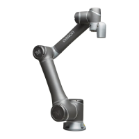
Figure 1: References of Joints by Models
2. Release the brake by pushing the pin on the brake solenoid shown in the following figures.
Base
1
st
Joint
Lower arm
6
th
Joint
3
rd
Joint
2
nd
Joint
Upper arm
TM5-700/ TM5M-700
4
th
Joint
5
th
Joint
1
st
Joint
Lower arm
6
th
Joint
3
rd
Joint
5
th
Joint
2
nd
Joint
Upper arm
TM5-900/ TM5M-900
Base
4
th
Joint
Upper arm
TM5X-700
1
st
Joint
Lower arm
4
th
Joint
6
th
Joint
5
th
Joint
Base
2
nd
Joint
3
rd
Joint
1
st
Joint
Lower arm
4
th
Joint
6
th
Joint
5
th
Joint
Upper arm
TM5X-900
Base
3
rd
Joint
2
nd
Joint

Table of Contents

Questions and Answers:

Question and Answer IconNeed help?

Do you have a question about the Omron Regular Payload and is the answer not in the manual?

Omron Regular Payload Specifications

General IconGeneral
BrandOmron
ModelRegular Payload
CategoryRobotics
LanguageEnglish

Related product manuals