Regular Payload Series-Hardware Installation Manual TM5 Series Hardware Version: 3.2 60
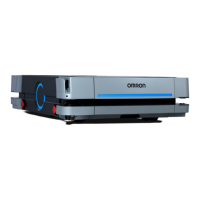
Pin Wire Color Pin Define
1 Black +24V 24V output
2 Brown DI_3 Digital Input3
3 Red DO_3
Digital
Output3
4 Orange AI Analog Input
5 Yellow +0V GND
*The M8/5PIN connector complies with the regulation of IEC 61076-2-104.
Table 14: 5-pin Analog I/O Connector of Cable
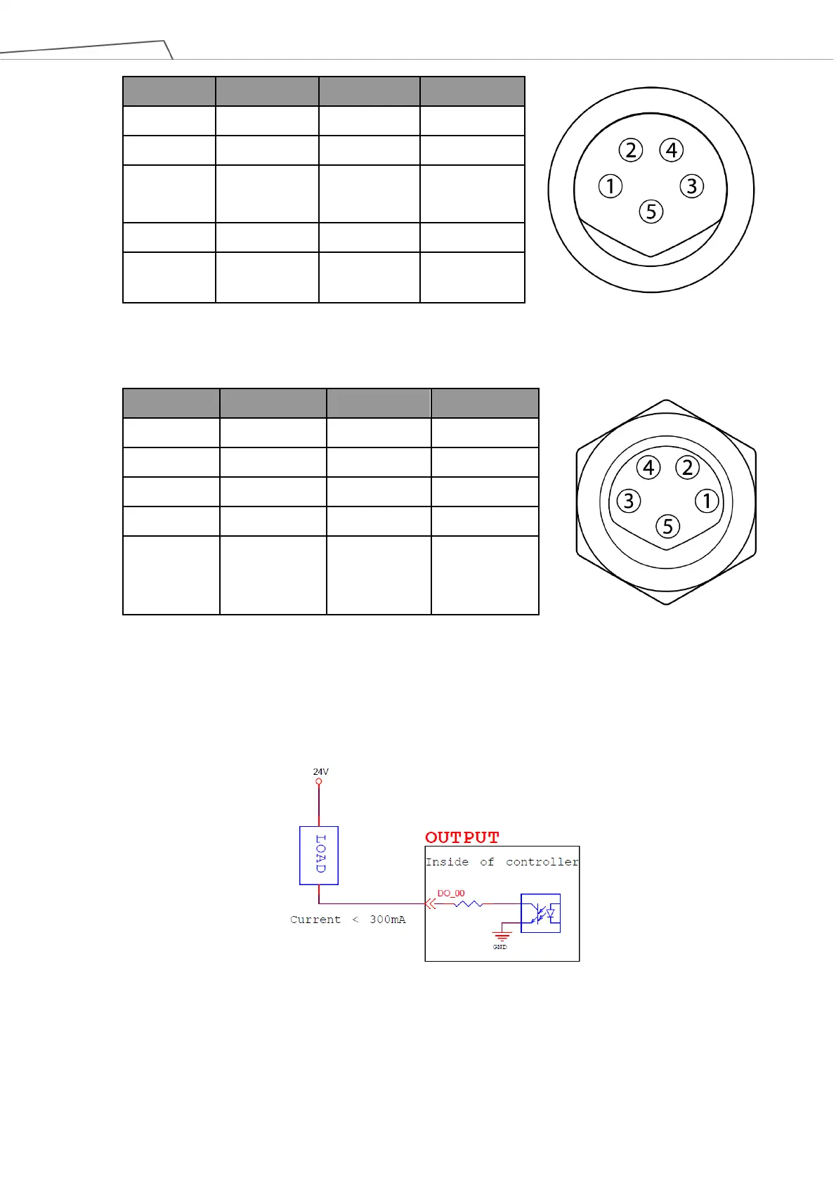
Pin Wire Color Pin Define
1 Black +24V 24V output
2 Brown DI_3 Digital Input3
3 Red DO_3 Digital Output3
4 Orange AI Analog Input
5 Yellow +0V GND
Table 15: 5-pin Analog I/O connector of Robot
5.4.2 Connecting Tool End Digital Output
The following figure shows how to connect the tool end digital output:
Figure 55: Connecting Tool End Digital Output
 Loading...