Regular Payload Series-Hardware Installation Manual TM5 Series Hardware Version: 3.2 42
4.2.4 Robot Light Module
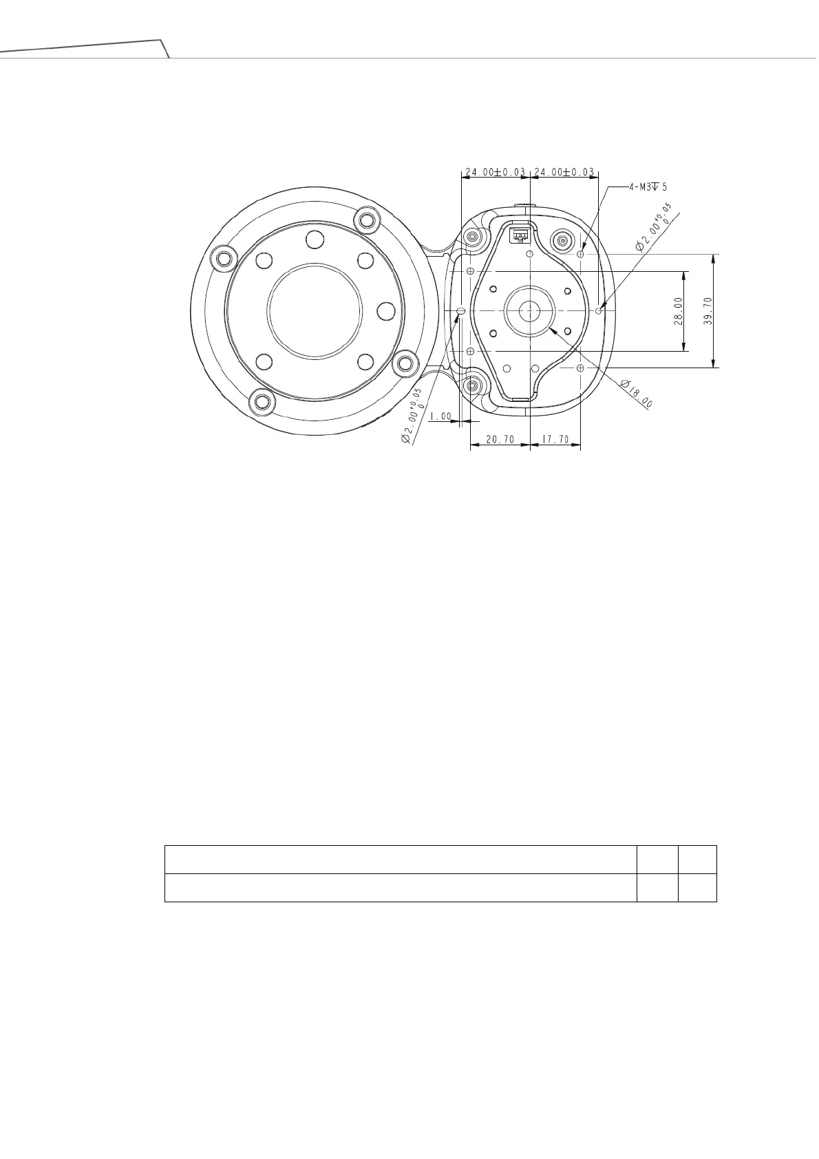
4.2.4.1 Light Module Surface
Figure 31: Light Module Surface
*All measures are in mm.
4.2.4.2 Install Light Module
The light module uses 4 of M3 screws to fix, and the recommended tightening torque is 1 Nm. For higher
accuracy on usages in demand, use both of the 2 mm diameter openings with the positioning pins to get
the better steadiness. Users can replace the light module by applications in demand. The choice
depends on the torque load of the light module, the available load of the robot, the possible influence the
other light module made to the camera's field of view, and the electrical specifications.
1. The torque load of the light module (M): this torque load must be lower than 900 kgf-mm, which is
the available strength of the camera module M3 screw can be loaded.
Calculation formula: M = (L+59.2)*W
The weight of the light module W kgf
The center of gravity of the light module L mm
Table 7: Reference of the Symbol and Unit in Calculation the Torque Load of the Light Module
 Loading...