3-7
3-2 Wiring
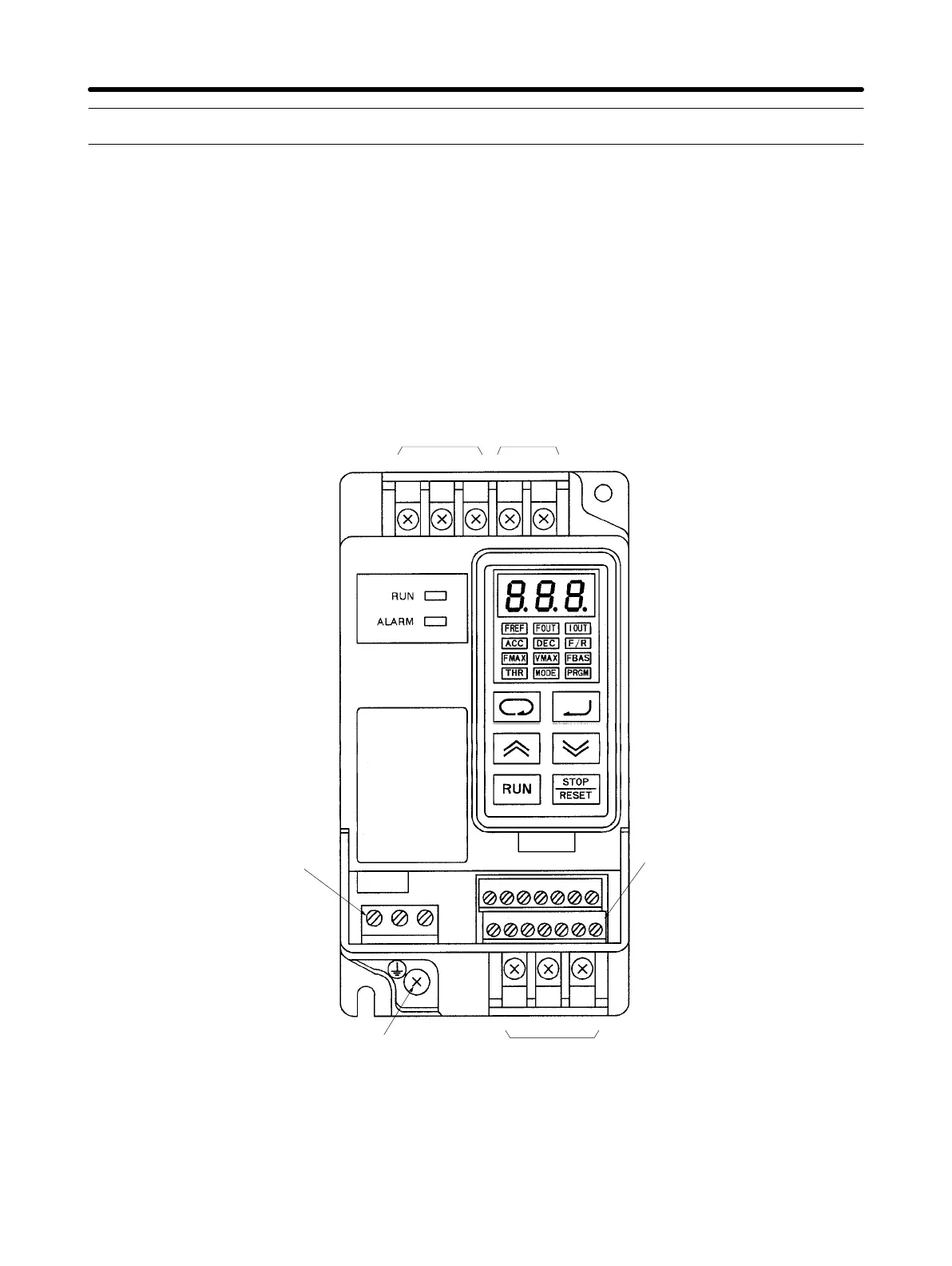
3-2-1 Terminal Blocks
H Name of Each Terminal Block
Main Circuit Terminals (Input)
Power input
terminals
Braking resistor
connection terminals
Control circuit terminals
(output)
Ground terminal
Main Circuit Terminals (Output)
Motor output
terminals
Control circuit terminals
(input/output)
MA MB MC
SF SR S1 SC FS FR FC
RS TB1B2
S2 S3 SC AM AC PA PC
UV W
Note This diagram shows an Inverter with all terminal block covers removed.
Design Chapter 3
 Loading...


