3-12
3-2-2 Wiring Around the Main Circuit
System reliability and noise resistance are affected by the wiring method
used. Therefore, always follow the instructions given below when connect-
ing the Inverter to peripheral devices and other parts.
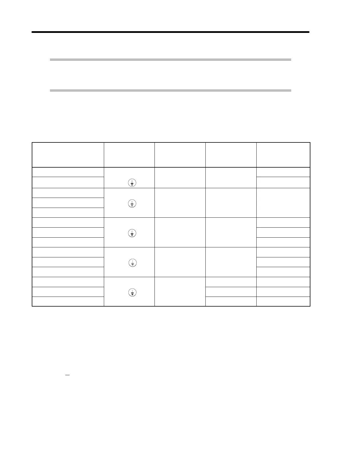
H Wire Size and Molded-Case Circuit Breaker to be Used
For the main circuit and ground, always use 600-V polyvinyl chloride (PVC) cables.
If the cable is long and may cause voltage drops, increase the wire size according to the
cable length.
Model Terminal
symbol
Terminal
screw
Wire size
(mm
2
)
Molded-case
circuit breaker
capacity (A)
3G3EV-A2001M(-j)
R S T B1 B2
M3.5 0.75 to 2
10
3G3EV-AB001M(-j)
U V W
5
3G3EV-A2002M(-j)
R S T B1 B2
M3.5 0.75 to 2 5
3G3EV-AB002M(-j)
U V W
3G3EV-A4002M(-j)
3G3EV-A2004M(-j)
R S T B1 B2
M3.5 0.75 to 2
5
3G3EV-AB004M(-j)
U V W
10
3G3EV-A4004M(-j)
5
3G3EV-A2007M(-j)
R S T B1 B2
M3.5 0.75 to 2
10
3G3EV-AB007M(-j)
U V W
20
3G3EV-A4007M(-j)
5
3G3EV-A2015M(-j)
R S T B1 B2
M3.5
0.75 to 2 20
3G3EV-AB015M(-j)
U V W
1.25 to 2 20
3G3EV-A4015M(-j)
0.75 to 2 10
Note Tighten the M3.5 terminal screw to the torque of 0.8 N S m.
Determining the Wire Size
Determine the wire size for the main circuit so that line voltage drop is within 2% of the
rated voltage.
Line voltage drop V
D
is calculated as follows:
V
D
(V) =
3
Ǹ
x wire resistance (Ω/km) x wire length (m) x amperage (A) x 10
–3
D Calculating the Inverter Input Power Supply Capacity
The following formula can generally be used to calculate the input power supply capac-
ity for the Inverter. Always select an Inverter with more than sufficient capacity.
Design Chapter 3
 Loading...


