3-19
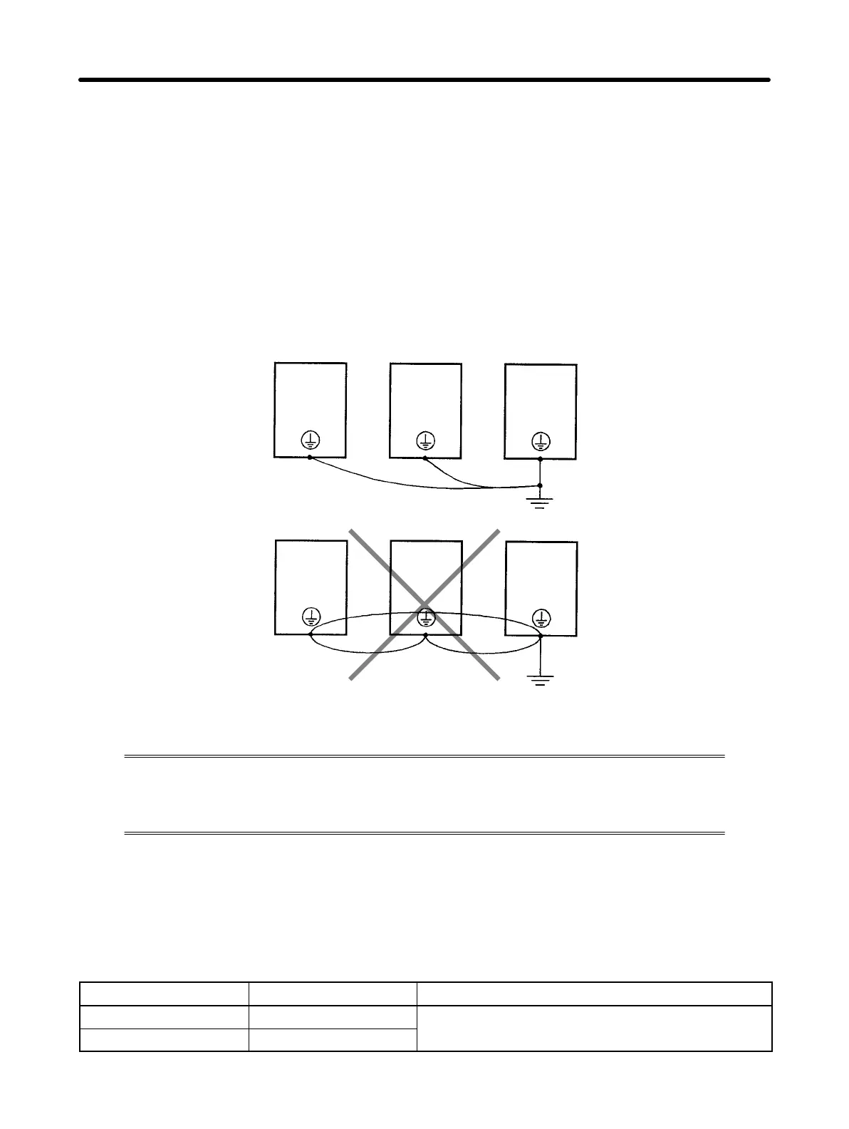
H Ground Wiring
•Always use a ground terminal with the following ground resistance.
200-VAC Class: 100 Ω or less
400-VAC Class: 10 Ω or less
•For 400-VAC-class models that conform to EC Directives, also connect to the neutral
of the power supply.
•Do not share the ground wire with other devices such as a welder or power tool.
•Always use a ground wire that complies with technical standards on electrical equip-
ment. Route the ground wire so that the total length is as short as possible.
•When using more than one Inverter, be careful not to loop the ground wire.
3-2-3 Wiring Control Circuit Terminals
The control signal line must be 50 m or less and must be separated from
the power line. If frequency references are input externally, use a twisted-
pair shielded line.
H Wiring Sequence Input/Output Terminals
Wire the sequence input terminals (SF, SR, S1 to S3, and SC), multi-function contact
output terminals (MA, MB, and MC), and multi-function photocoupler output terminals
(PA and PC) as described below.
D Wires to be Used
Wire type Wire size Wire to be used
Single wire 0.5 to 1.25 mm
2
Polyethylene-shielded cable
Stranded wire 0.5 to 0.75 mm
2
Design Chapter 3
 Loading...


