5-2
5-1 Protective and Diagnostic Functions
The RUN and ALARM indicators on the front panel of the Inverter indicate
the current status of the Inverter and the data display section displays in-
formation about an error that has occurred.
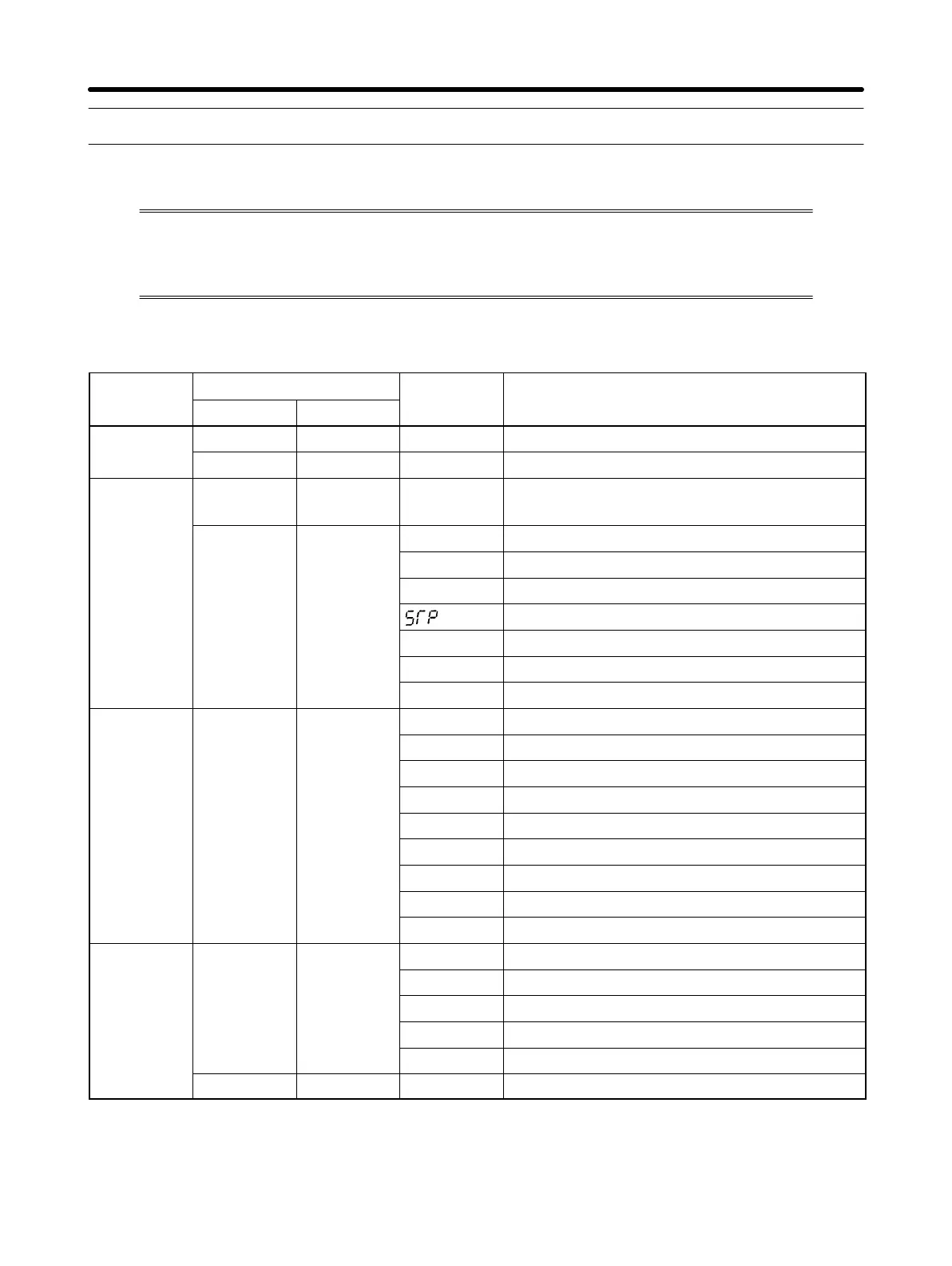
H List of Error Codes
Inverter
Indicator
Data Description
status
RUN ALARM
display
Normal
Flashes Not lit --- Ready to run
Lit Not lit --- Normal operation in progress
Warning
Flashes Flashes
ef
Simultaneous input of forward and re-
verse rotation commands
Lit Flashes
uU
Main circuit undervoltage (UV)
%U
Main circuit overvoltage (OV)
%h
Radiation fin overheated (OH)
Digital Operator stopped (STP)
%l3
Over-torque (OL3)
bb
External base block in progress (bb)
ser
Sequence error (SEr)
Protective Not lit Lit
%c
Overcurrent (OC)
mecha-
%U
Main circuit overvoltage (OV)
nism actu-
uU1
Main circuit undervoltage (UV1)
ated
uU2
Control power supply fault (UV2)
%h
Radiation fin overheated (OH)
%l1
Motor overload (OL1)
%l2
Inverter overload (OL2)
%l3
Over-torque (OL3)
ef1
External fault (EF1)
Inverter Not lit Lit
f00
Initial memory error
error
f01
ROM error
f04
Constant error
f05
A/D converter error
f06
Option error
Not lit Not lit (Not lit) Control circuit error
Note EF2 or EF3 will be displayed if an external error is input from multi-function input 2
or 3.
Operation Chapter 5
 Loading...


