5 Setup and Wiring
5 - 22
Vision System FH/FZ5 series Hardware Setup Manual (Z366)
Power Supply and Wiring
• Never connect AC power to this product. Connecting an AC power source may cause a mal-
function.
• The recommended power supply is S8VS-
24 (made by OMRON) or S8VK-G-24
(made by OMRON).
• Keep the power supply wires as
short as possible (Max.10 m).
• Use the cables and crimping termin
als with the specified dimensions.
Do not directly connect an electric wire to the terminal
lock that is simply twisted.
• Recommended wire size: AWG16 to 13 (1.31 to 2.63 mm
2
)
• Terminal screw: M4 (Tightening torque: 1.4 N·m)
• Crimping Terminal
• After wiring, replace the terminal cover.
Ground
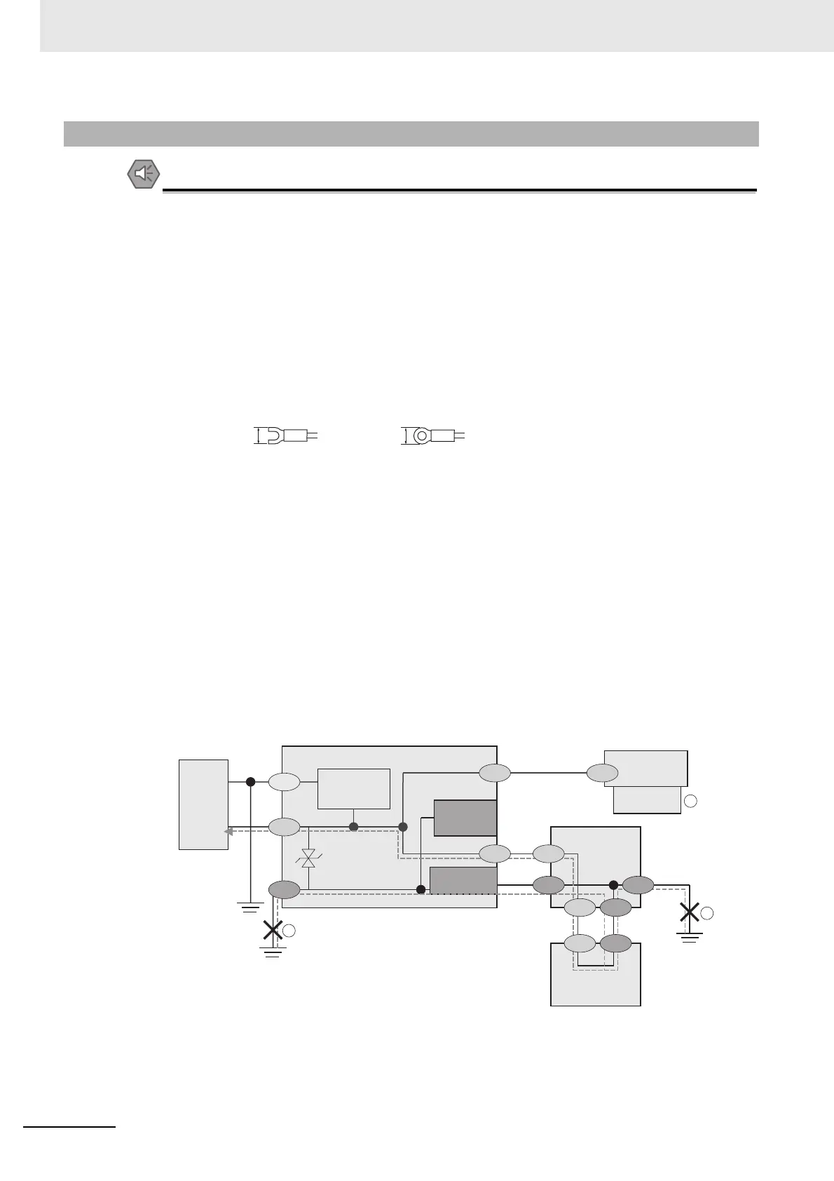
• The controller power circuit is not insulated from its internal circuit.
• When grounding the 24 V DC power supply’ s positive terminal, do not ground the controller’
s FG
terminal or the PLC’ s FG terminal. [, ] Since the PC’ s shell and the SG (0V) are
con
nected inside the PC, current would run through the route shown in the figure below and
cause burnout.
• As in the case with a PC, you can safely ground the controller’ s FG terminal without a prob-
lem when there is no possibility that the SG (0V) and the FG will short-circ
uit. For information
about the PLC wiring, check the specifications of your PLC before wiring.
• Be sure to use a pedestal when connecting a camera to the controller. [] As the shell of the
ca
mera is the SG (0V), it can cause short-circuiting between the SG (0V) and the FG if a
pedestal is not used.
• To avoid receiving an electric shock when groun
ding a positive terminal, do not touch the SG
(0V) (camera, power supply terminal).
5-3-4 FZ5 Series
1
2
3
SG (0 V)
0V
SG SG
24 V
SG
SG
FG
FG FG
RS-232C
RS-232C
SG
SG
SG FG
FG
PLC
FG
Power
supply
Controller
Camera cable
SG (0 V)
Camera
Mounting Spacer
(insulator)
Power supply
circuit
PC
Shell
Parallel I/O
connectorʼs
shell
RS-232C
connector
ʼ
s shell
SG: Signal Ground
FG: Frame Ground

 Loading...

