NHC,
NHCV
Installation Guidelines
VENTILATION
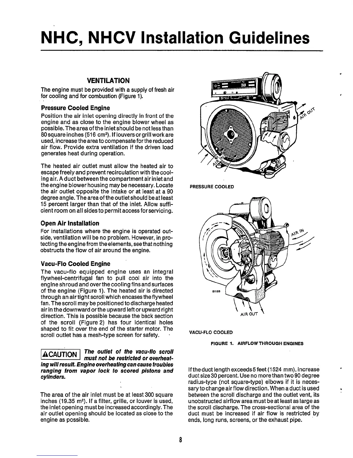
The engine must be provided with a supply of fresh air
for cooling and for combustion (Figure
1).
Pressure Cooled Engine
Position the air inlet opening directly in front of the
engine and as close to the engine blower wheel as
possible.Theareaoftheinletshould
be not lessthan
80
square inches
(516
cm'). If louvers or grill work are
used, increase thearea to compensate forthe reduced
air flow. Provide extra ventilation if the driven load
generates heat during operation.
The heated air outlet must allow the heated air to
escape freely and prevent recirculation with thecool-
ing air. A duct between the compartment air inlet and
theengine blower housing may be necessary. Locate
the air outlet opposite the intake or at least at a
90
degree angle. The area of the outlet should be at least
15
percent larger than that of the inlet. Allow suffi-
cient room on all sides to permit access forservicing.
Open Air Installation
For installations where the engine is operated out-
side, ventilation will be no problem. However, in pro-
tecting theengine from theelements, seethat nothing
obstructs the flow of air around the engine.
Vacu-Flo
Cooled Engine
The vacu-flo equipped engine uses an integral
flywheel-centrifugal fan to pull cool air into the
engine shroud and over the cooling finsand surfaces
of the engine (Figure
1).
The heated air is directed
through an airtight scroll which encasestheflywheel
fan. The scroll may be positioned to discharge heated
air in the downward orthe upward left or upward right
direction. This is possible because the back section
of the scroll (Figure2) has four identical holes
shaped to fit over the end of the starter motor. The
scroll outlet has a mesh-type screen for safety.
.
The ouflef
of
the vacu-flo scroll
@!@%I
musf nof be resfricfed or overheaf-
ing will result. Engine overhea fing can cause troubles
ranging
from
vapor lock
to
scored pistons and
cylinders.
The area of the air inlet must be at least
300
square
inches
(19.35
m2).
If
a filter, grille, or louver
is
used,
the inlet opening must be increased accordingly. The
air outlet opening should be located as close to the
engine
as
possible.
PRESSURE COOLED
m
PRESSURE COOLED
m
VACU-FLO
COOLED
FIGURE
1.
AIRFLOW
THROUGH ENGINES
Iftheduct length exceeds5feet
(1524
mm), increase
duct size
30
percent. Use no more than two
90
degree
radius-type (not square-type) elbows if
it
is neces-
sary to change air flow direction. When aduct is used
between the scroll discharge and
the
outlet vent, its
unobstructed airflow area must be at least as large as
the scroll discharge. The cross-sectional area of the
duct must be increased if air flow is restricted by
ends, long runs, screens, or the exhaust pipe.
b
8
 Loading...

