Electric Fuel
Pump
All engines used on Onan
N
series generator sets are
equipped with an electric fuel pump. The pump is
manufactured by Facet (a division of Bendix Corpo-
ration) and carries a Facet nameplate. An internal fuel
shutoff valve is a standard feature on this pump.
Older versions
of
this pump carry the Bendix name-
plate and do not have an internal fuel shutoff valve.
Service proceduresforthe Facet or Bendix pump are
the same.
Do
not substitute automotive type
laWAR”Gl
electric fuel pumps for standard
Onan supplied electric pumps. The
output
pressure
is much higher and can cause carburetor flooding
or
fuel
leakage, creafing a fire hazard.
Pump
Tesf:Test the fuel pump by checking the pump
outlet pressure. Use the following procedure.
1.
2.
3.
Remove the fuel line from the pump outlet and
install a pressure gauge.
Press the START switch and hold
it
for several
seconds until pressure reading is constant.
Pressure reading should be 2-1/2 to
3-1/4
psi
(17.2 to 22.4 kPa). If the retension is good, the
pressure should stay constant or drop
off
very
slowly.
A low pressure reading with little or no pressure drop
indicates a weak or broken diaphragm or diaphragm
spring, worn linkage,or leaky check valves. If pressure
is above maximum, the pump diaphragm is too tight
or the diaphragm (or plunger) return spring is too
strong. Any of the above conditions are cause for
repair or replacement of the pump.
Fuel Pump Repair:
Service of the Facet pump
is
limited to the bottom cover, filter, plunger tube, and
plunger assembly. All parts
of
the electric system are
hermetically sealed in a gas atmosphere and are not
serviceable. If electrical failure occurs, replace the
Pump.
Do
not tamper with the seal at the
@%@@
cenfer
of
fhe mounting bracket
on
the side of the pump as
if
retains the dry gas which
surrounds fhe electrical system. Electrical system
components are nof serviceable.
Use the following procedure for servicing the pump:
1.
Using a5/8-inch wrench, loosen, the pump cover,
then remove by hand.
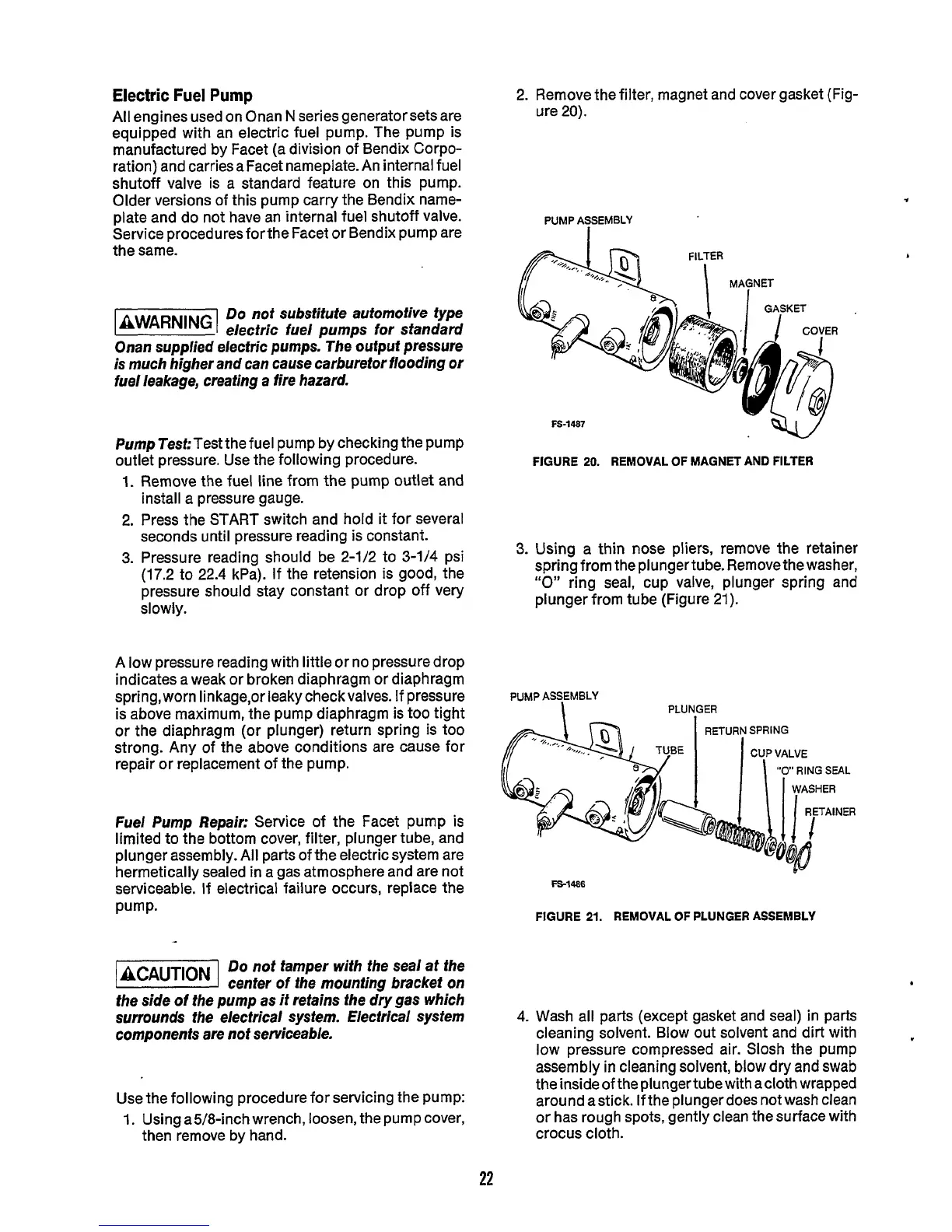
2. Remove the filter, magnet and cover gasket (Fig-
ure 20).
PUMP ASSEMBLY
I
3.
FS-1487
FIGURE
20.
REMOVAL
OF
MAGNET AND FILTER
Using a thin
nose
pliers, remove the retainer
spring from the plungertube. Remove the washer,
“0”
ring seal, cup valve, plunger spring and
plunger from tube (Figure
21).
PUMP ASSEMBLY
PLU
N,GER
FS-1486
FIGURE
21.
REMOVAL
OF
PLUNGER ASSEMBLY
4.
22
Wash all parts (except gasket and seal) in parts
cleaning solvent. Blow out solvent and dirt with
low pressure compressed air. Slosh the pump
assembly
in
cleaning solvent, blow dry and
swab
the inside of the plunger tube with acloth wrapped
around astick. lfthe plungerdoes notwash clean
or has rough spots, gently clean the surface with
crocus cloth.
 Loading...

