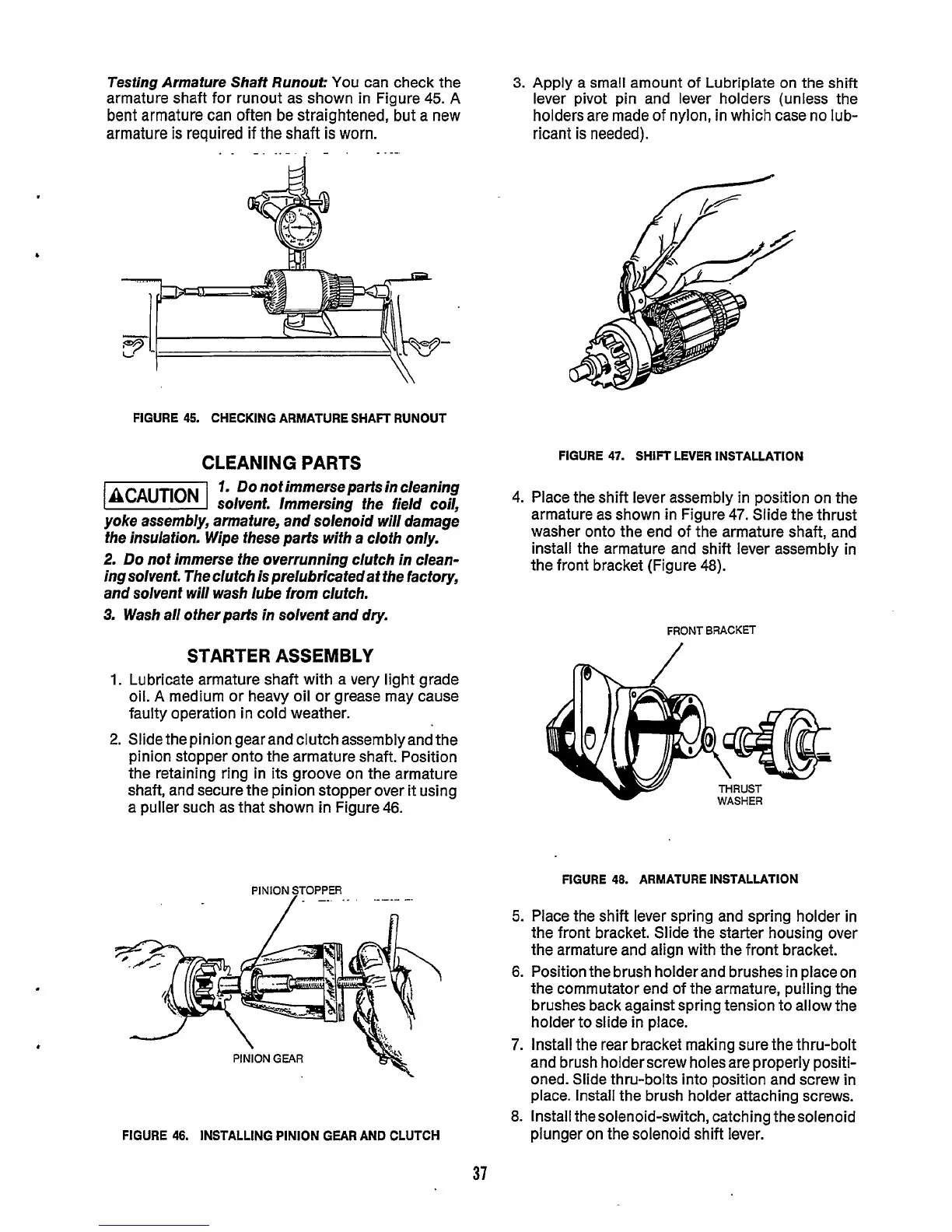
Testing Armature
Shaff
Runout:
You can check the
armature shaft for runout as shown in Figure
45.
A
bent armature can often be straightened, but a new
armature
is
required if the shaft
is
worn.
FIGURE
45.
CHECKING ARMATURE SHAFT RUNOUT
CLEANING PARTS
1.
Do
not immerse parts in cleaning
(BCAUTIONI
solvent. Immersing the field coil,
yoke assembly, armature, and solenoid will damage
fhe insulafion. Wipe these parts with a cloth only.
2.
Do
nof
immerse fhe overrunning clutch in clean-
ing solvent- The clutch
is
prelubricafedat the factory,
and solvent will wash lube from clutch.
3.
Wash all other parts in solvent and dry.
STARTER ASSEMBLY
1.
Lubricate armature shaft with a very light grade
oil.
A
medium or heavy oil or grease may cause
faulty operation in cold weather.
2.
Slide the pinion gear and clutch assembly and the
pinion stopper onto the armature shaft. Position
the retaining ring in its groove on the armature
shaft, and secure the pinion stopper over it using
a puller such as that shown in Figure 46.
3.
Apply a small amount of Lubriplate on the shift
lever pivot pin and lever holders (unless the
holders are made
of
nylon, in which case no lub-
ricant
is
needed).
FIGURE
47.
SHIFT LEVER INSTALLATION
4. Place the shift lever assembly in position on the
armature as shown in Figure 47. Slide the thrust
washer onto the end of the armature shaft, and
install the armature and shift lever assembly in
the front bracket (Figure 48).
FRONT
BRACKET
I
FIGURE
46.
ARMATURE INSTALLATION
PINION
STOPPER
..
,
-.
5.
Place the shift lever spring and spring holder in
the front bracket. Slide the starter housing over
the armature and align with the front bracket.
6.
Position the brush holder and brushes in place on
the commutator end of the armature, pulling the
brushes back against spring tension to allow the
holder to slide in place.
7.
Install the rear bracket making sure the thru-bolt
and brush holder screw holes are properly positi-
oned. Slide thru-bolts into position and screw
in
place. Install the brush holder attaching screws.
8. Install thesolenoid-switch, catching the solenoid
plunger on the solenoid shift lever.
FIGURE
46.
INSTALLING PINION GEAR
AND
CLUTCH
37
 Loading...

