INSPECTION
AFTER
OVERHAUL
For no-load test, the starting motor is wired as
shown in Figure
49
and run. The value of the
meter reading at this condition should be as
follows:
Begin Spec
B
Voltage 10.5 11.5
RPM
5000
3700
Max. Current
Draw (Amp)
53
60
Spec
A
Only
1.
AMMETER
SWITCH
INDICATOR
FIGURE
49.
WIRING STARTER FOR NO-LOAD TESTS
The conductor for this test should be large enough in
diameter and as short as possible.
If
anything
is
wrong in
the above test, inspect the following items:
Annealed brush springs
Improperly sealed brushes
Insufficient armature endplay
Shorted, open, or grounded armature
Grounded or open field coil
Poor electrical connection
Dirty commutator
2.
To
adjust pinion clearance, connect the battery to
thestarting motorasshown in Figure50.This will
allow the pinion of the starting motor to slide and
stop. In this state, measure the clearance between
the end of the pinion and pinion stop when the
pinion
is
pushed lightly toward the commutator
end. Clearance should be
0.02
to
0.06
inch (0.51
to 1.52 mm). Adjust for proper clearance by
removing the solenoid switch attaching screws
and select the proper thickness of the fiber
packings shown
in
Figure
51.
FIBER
PACKINGS
FIGURE
51.
ADJUSTING PINION CLEARANCE
CHECKING
GEAR
LASH
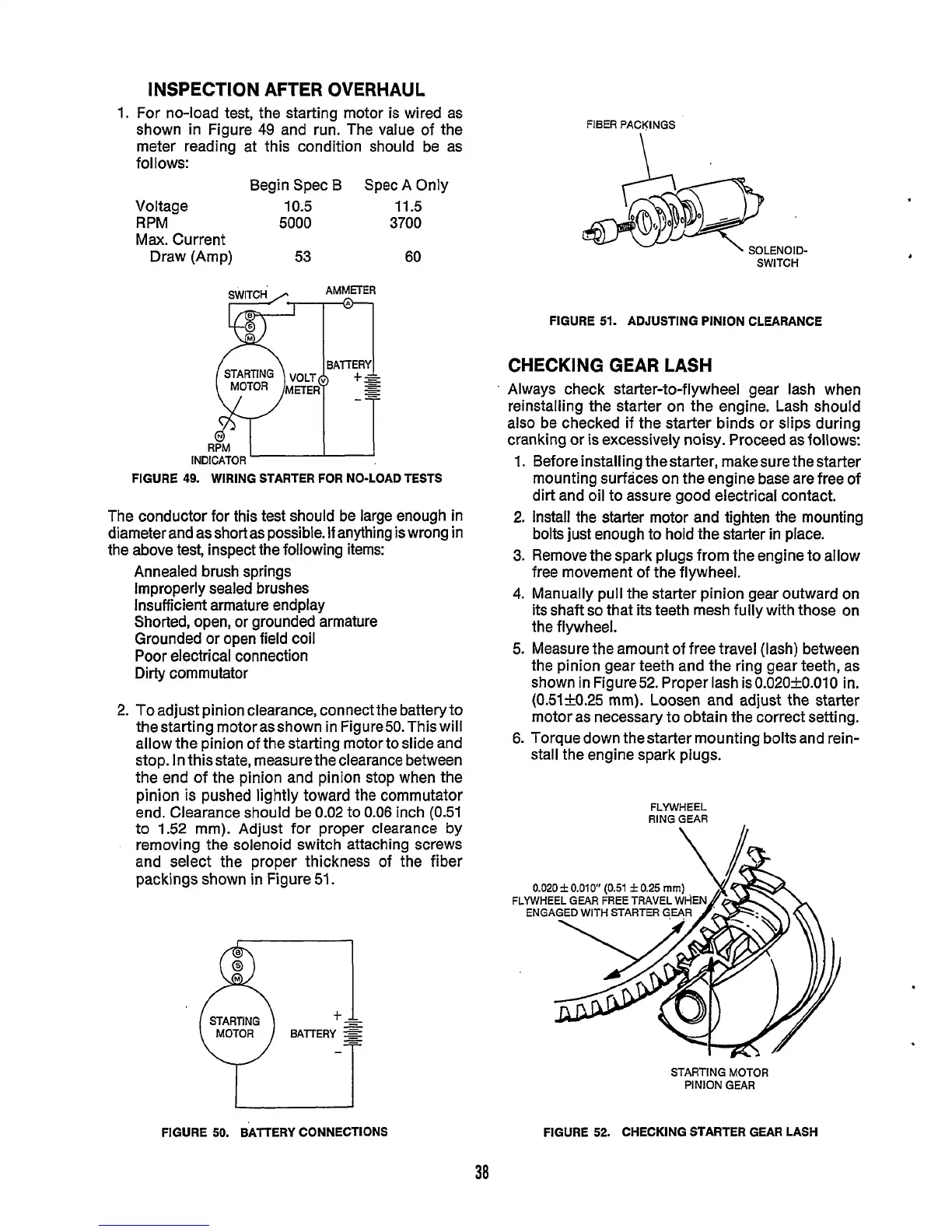
Always check starter-to-flywheel gear lash when
reinstalling the starter on the engine. Lash should
also be checked if the starter binds or slips during
cranking or
is
excessively noisy. Proceed as follows:
1.
2.
3.
4.
5.
Before installing thestarter, make sure
the
starter
mounting surfaces on the engine base are free of
dirt and oil to assure good electrical contact.
Install the starter motor and tighten the mounting
bolts just enough to hold the starter in place.
Remove the spark plugs from the engine to allow
free movement of the flywheel.
Manually pull the starter pinion gear outward on
its shaft
so
that
its
teeth mesh fully with those on
the flywheel.
Measure the amount of free travel (lash) between
the pinion gear teeth and the ring gear teeth, as
shown in Figure52. Proper lash isO.O20+0.010 in.
(0.51+_0.25 mm). Loosen and adjust the starter
motor as necessary to obtain the correct setting.
6.
Torque down thestarter mounting bolts and rein-
stall the engine spark plugs.
FLYWHEEL
RING
GEAR
0.020
f
0.010''
(0.51
f
0.25
mm)
FLYWHEEL
GEAR FREE
TRAVEL
WHE
ENGAGED WITH
STARTER
G.EqR
STARTING
MOTOR
PINION
GEAR
FIGURE
50.
BATTERY
CONNECTIONS
38
FIGURE
52.
CHECKING STARTER GEAR LASH
 Loading...

