No
Output-Stator Assembly:
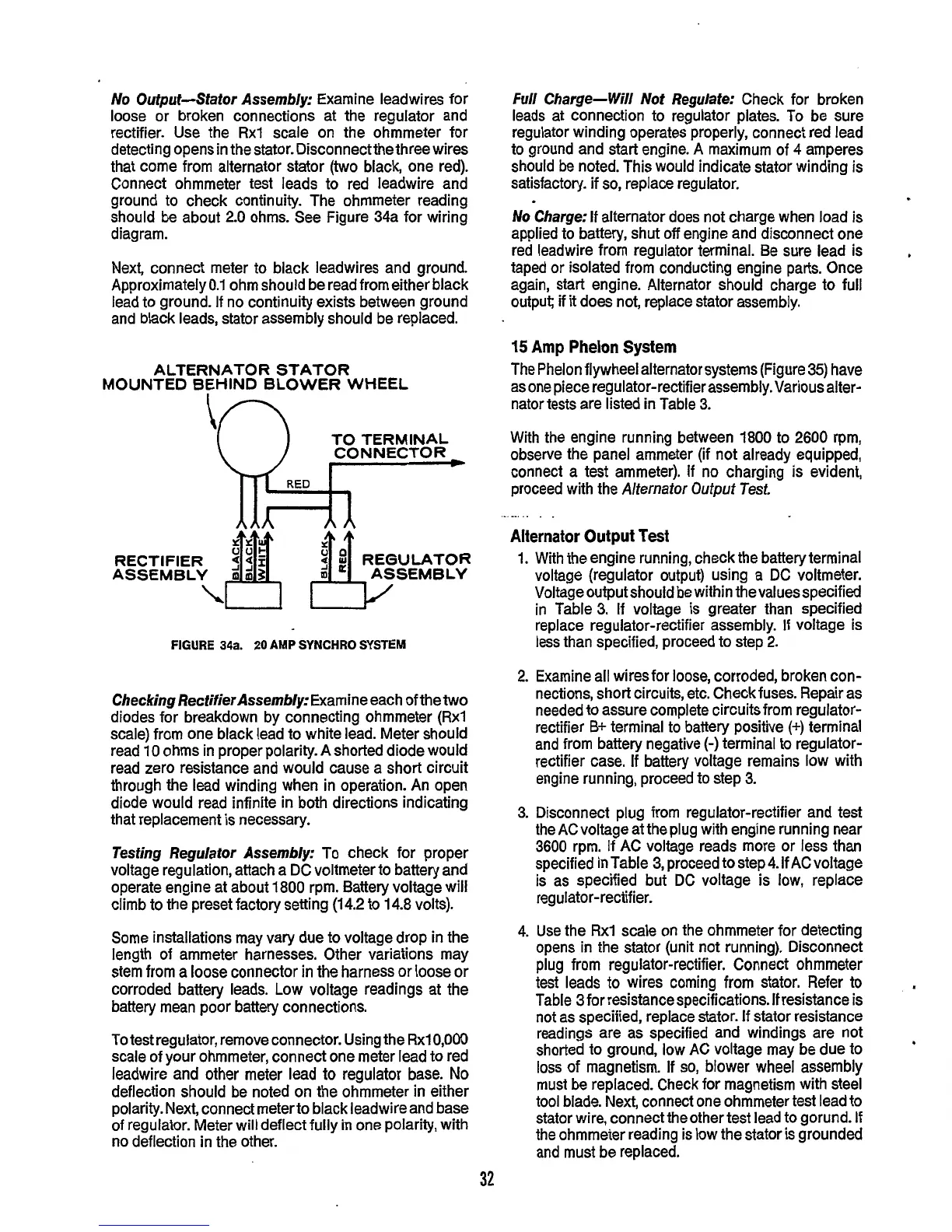
Examine leadwires for
loose or broken connections at the regulator and
rectifier. Use the
Rxl
scale on the ohmmeter for
detecting opens in the stator. Disconnectthe three wires
that come from alternator stator
(two
black, one red).
Connect ohmmeter test leads to red leadwire and
ground to check continuity. The ohmmeter reading
should be about 2.0 ohms. See Figure 34a for wiring
diagram.
Next, connect meter to black leadwires and ground.
Approximately0.1 ohm should be read from either black
lead to ground. If no continuity exists between ground
and black leads, stator assembly should be replaced.
ALTERNATOR STATOR
MOUNTED BEHIND BLOWER WHEEL
\n
TO TERMINAL
CONNECTOR
RECTIFIER
ASSEMBLY ASSEMBLY
I
--
-
FIGURE
34a.
20
AMP
SYNCHRO
SYSTEM
Checking RectifierAssembly:
Examine each of the
two
diodes for breakdown by connecting ohmmeter (Rxl
scale) from one black lead to white lead. Meter should
read 10 ohms in proper polarity. A shorted diode would
read zero resistance and would cause a short circuit
through the lead winding when in operation. An open
diode would read infinite in both directions indicating
that replacement is necessary.
Testing Regulator Assembly:
To check for proper
voltage regulation, attach a DC voltmeter to battery and
operate engine at about 1800 rpm. Battery voltage will
climb to the preset factory setting
(14.2
to 14.8 volts).
Some installations may vary due to voltage drop in the
length of ammeter harnesses. Other variations may
stem from a loose connector
in
the harness or loose or
corroded battery leads. Low voltage readings at the
battery mean poor battery connections.
To test regulator, remove connector. Using the Rxl0,OOO
scale of your ohmmeter, connect one meter lead to red
leadwire and other meter lead to regulator base.
No
deflection should be noted on the ohmmeter in either
polarity. Next, connect meter to black leadwire and base
of regulator. Meter will deflect fully in one polarity, with
no deflection in the other.
Full
Charge-
Will
Not Regulate:
Check for broken
leads at connection to regulator plates. To be sure
regulator winding operates properly, connect red lead
to ground and start engine.
A
maximum of
4
amperes
should be noted. This would indicate stator winding is
satisfactory. if
so,
replace regulator.
No
Charge:
If alternator does not charge when load is
applied to battery, shut
off
engine and disconnect one
red leadwire from regulator terminal. Be sure lead is
taped or isolated from conducting engine parts. Once
again, start engine. Alternator should charge to full
output; if
it
does not, replace stator assembly.
6
15
Amp Phelon System
The Phelon flywheel alternator systems (Figure
35)
have
as one piece regulator-rectifier assembly. Various alter-
nator tests are listed in Table
3.
With the engine running between 1800 to 2600 rpm,
observe the panel ammeter (if not already equipped,
connect a test ammeter).
If
no charging is evident,
proceed with the
Alternator
Output
Test,
Alternator Output
Test
...
.
.
.
.
1.
With the engine running, check the battery terminal
voltage (regulator output) using a DC voltmeter.
Voltage output should be within thevaluesspecified
in Table
3.
If voltage is greater than specified
replace regulator-rectifier assembly.
If
voltage is
less than specified, proceed to step
2.
2.
Examine all wires for loose, corroded, broken con-
nections, short circuits, etc. Check fuses. Repair as
needed to assure complete circuits from regulator-
rectifier
B+
terminal to battery positive
(+)
terminal
and from battery negative
(-)
terminal to regulator-
rectifier case.
If
battery voltage remains low with
engine running, proceed
to
step
3.
3.
Disconnect plug from regulator-rectifier and test
the
AC
voltage at the plug with engine running near
3600 rpm. If AC voltage reads more or less than
specified in Table 3, proceed to step 4. If ACvoltage
is as specified but
DC
voltage is low, replace
reg ulator-rectifier.
4.
Use the Rxl scale on the ohmmeter for detecting
opens in the stator (unit not running). Disconnect
plug from regulator-rectifier. Connect ohmmeter
test leads
to
wires coming from stator. Refer to
Table
3
for
resistancespecifications.
If resistance is
not as specified, replace stator. If stator resistance
readings are as specified and windings are not
shorted to ground, low AC voltage may be due to
loss of magnetism. If
so,
blower wheel assembly
must be replaced. Check for magnetism with steel
tool blade. Next, connect one ohmmeter test lead to
stator wire, connect the other test lead to gorund. If
the ohmmeter reading is low the stator
is
grounded
and must be replaced.
32
 Loading...

