1
Warpage occurs chiefly in the upper stem due to its
exposure to intense heat. Out-of-round wear follows
when the seat is pounded by a valve whose head is
not in line with the stem and guide. If
a
valve face is
burned or warped, or
if
the stem is worn, install a new
valve.
Too
much clearance in the intake guide admits air
and oil into the combustion chamber, upsetting
carburetion, increasing oil consumption, and making
heavy carbon deposits. Carbon reduces heat dissi-
pation. Clean metal is a good heat conductor' but
carbon insulates and retains heat. This increases
combustion chamber temperatures which causes
warping and burning.
Unburned carbon residue gums valve stems and
causes them to stick in the guide. Deposits of hard
carbon with sharp points projecting become white
hot and cause pre-ignition and pinging.
Refinish valves that are slightly pitted or burned on an
accurate valve grinder. If valves are badly pitted or
have a thin margin when refacing, replace them.
VT-1020
FIGURE
54.
VALVE STEM AND VALVE GUIDE INSPECTION
Sfems And Guides:
Always check valve stems and
guides for wear (Figure
54).
Use
a
hole gauge to
measure the valve guide. When clearance with stem
exceeds that specified in
DIMENSIONS AND CLEAR-
ANCES,
replace either valve or guide or both,
as
may be
necessary. Always regrind seatto make concentric with
the newly installed guide.
Worn valve stem guides can be replaced from inside
the valve chamber (a seal is provided behind the
intake valve guides only). The smaller diameter of the
tapered valve guides must face toward the valve head.
Tappets are also replaceable from the valve chamber
after first removing the valve assemblies.
Valve Guide Removal:
Before removing valve guides,
use
an electric drill with a wire brush
to
remove
carbon and otherforeign material from top surfaceof
guides. Failure to perform this operation may result in
damage
to
the guide bores. Drive the guides out with
a
hammer and valve guide driver.
Driving
out
old guides can damage
fhe tappet bores. Be careful not
to
sfrike bores
wifh
driver.
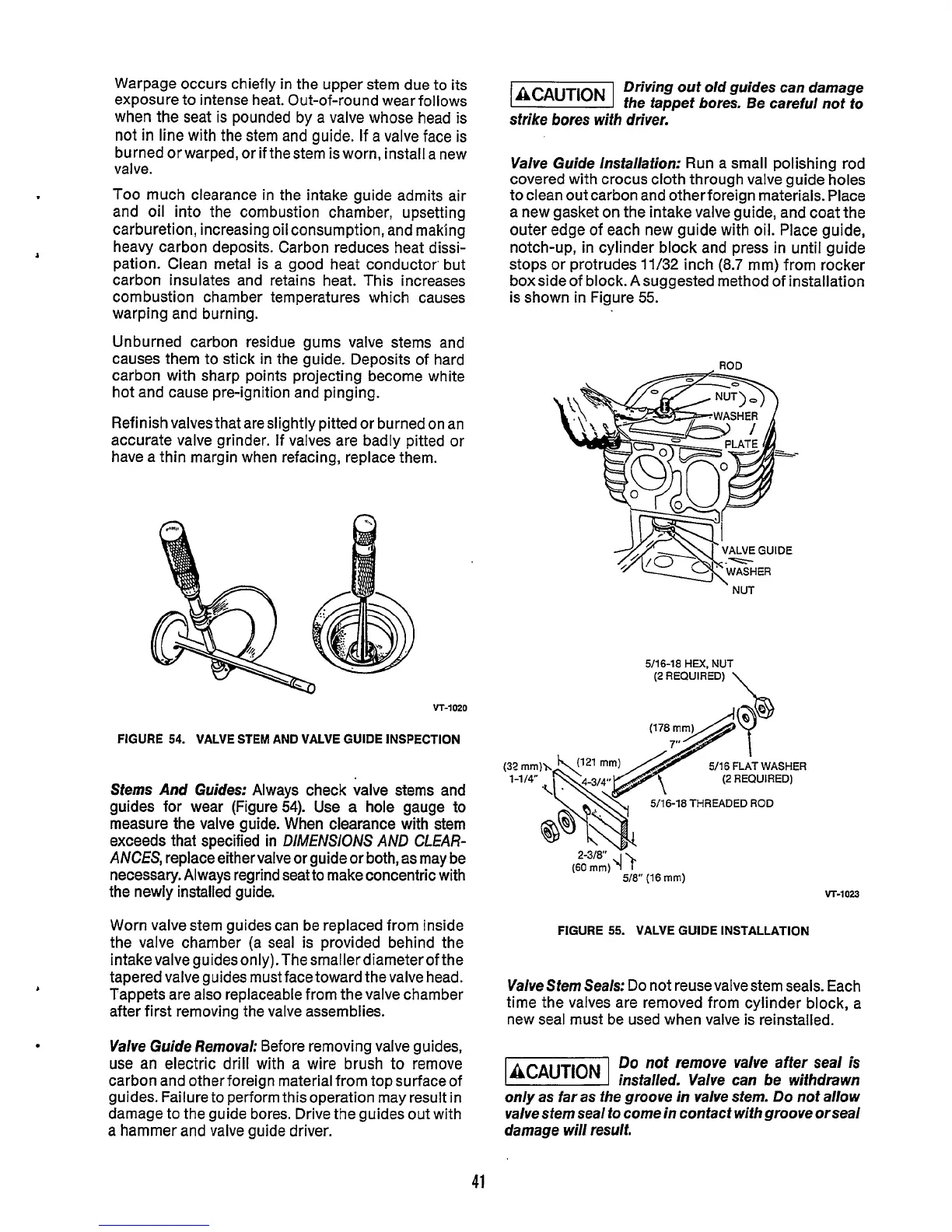
Valve Guide lnsfallafionr
Run a small polishing rod
covered with crocus cloth through valve guide holes
to clean out carbon and otherforeign materials. Place
a new gasket on the intake valve guide, and coat the
outer edge of each new guide with oil. Place guide,
notch-up, in cylinder block and press in until guide
stops or protrudes
11/32
inch
(8.7
mm) from rocker
boxside of block. Asuggested method of installation
is shown in Figure
55.
ROD
'
NUT
5/16-18
HEX.
NUT
\
(2
REQUIRED)
5/16
FLAT
WASHER
(2
REQUIRED)
-18
THREADED ROD
(Elm)
T-
5/8"
(16
mm)
vr-1023
FIGURE
55.
VALVE GUIDE INSTALLATION
Valve Stem Seals:
Do
not reuse valve stem seals. Each
time the valves are removed from cylinder block, a
new seal must be used when valve is reinstalled.
Do
not
remove valve after seal
is
insfalled. Valve can be wifhdrawn
only as far as the groove in valve stem. Do not allow
valve stem seal
fo
come in confacf
wifh
groove orseal
damage will result.
41
 Loading...

