11
Connection
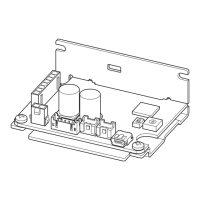
Using external DC voltage
For the external voltage, use a DC power supply (0 to 5 VDC) with
reinforced insulation on its primary and secondary sides, and
connect to the pin No.4 and No.5 of the CN2.
Input impedance between the VM input and VL input is
approximately 47 k
Ω
.
The VL input is connected to GND inside the driver.
External DC
power supply
0 to 5 VDC
1 mA or more
VM
VL
(CN2)
Green
Yellow
5
4
+
–
Note
•
Be sure to use the voltage of an external control device at 5 VDC or lower.
When connecting an external control device, make sure the polarities are correct. If the polarities are reversed, the
driver may be damaged.
•
When a shielded cable is used for connection with the external control device, connect shields to VL of the pin No.4
from near the I/O signal connector (CN2).
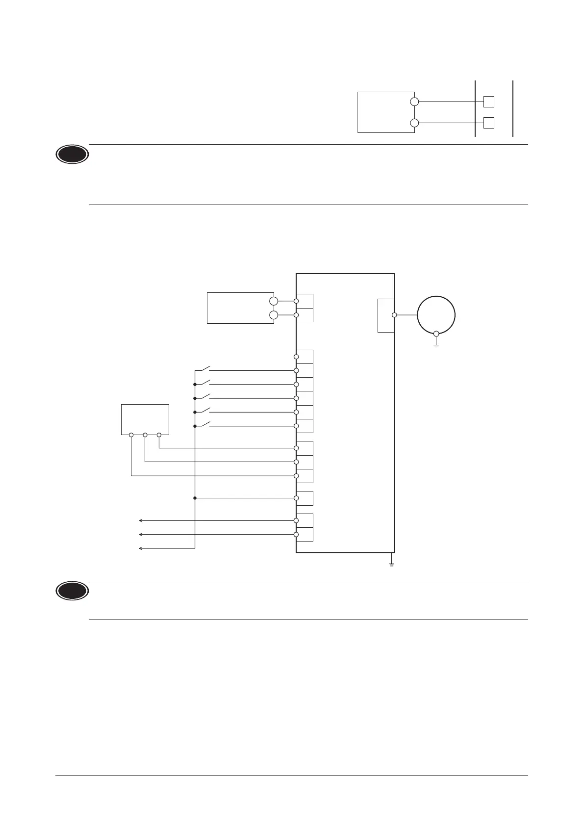
6.7 Connection diagram
The gure shows an example when an external potentiometer is connected.
External potentiometer
PAVR2-20K
(sold separately)
21
3
0 to 20 kΩ
o external
e
Motor connector
CN3
DIN0 (START/STOP)
11
N.C.
12
CN2
10
9
8
7
6
DIN1 (RUN/BRAKE)
DIN2 (FWD/REV)
DIN3 (M0)
DIN4 (ALM-RST)
VH
5
VM
4
VL
3
GND
DOUT0 (SPEED-OUT)
DOUT1 (ALM-B)
Connecting the motor
Motor
2
1
Connecting output signals
Connecting input signals
CN1
24 VDC±10%
DC power supply
–
+
+
–
Note
Insulate unused lead wires which are on the opposite side to the connector of the I/O signal cable to prevent them
from contacting other devices, or connect them to 5 VDC or the signal ground (GND) of your external control device
according to usage of signals.
 Loading...