9
Connection
6.3 Grounding
The wire used to ground the motor and driver must be as thick and short to the grounding point as possible so that no
potential dierence is generated. Choose a large, thick and uniformly conductive surface for the grounding point.
z
Grounding the motor
Connect the grounding wire along with a set
screw to the grounding point, using a shakeproof
washer.
For the 15 W type motor, remove the paint from
the mounting surface of the geared motor, and
install it to a metal surface that has grounded.
z
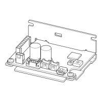
Grounding the driver
Install the driver to a metal surface that
has grounded.
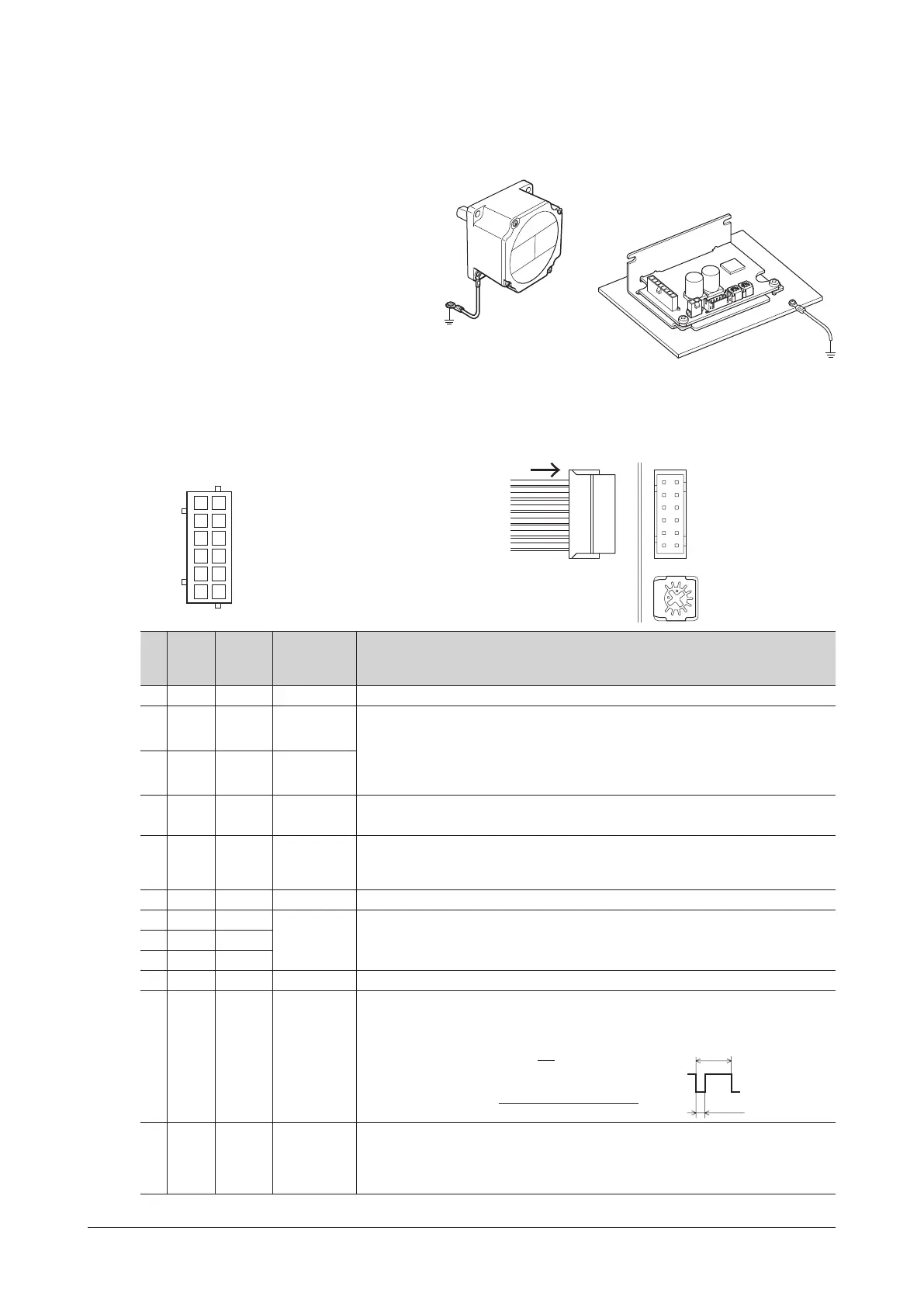
6.4 Connecting the I/O signals (CN2)
Insert the connector of the I/O signal cable into the I/O signal connector (CN2) of the driver.
Lead wire size: AWG26 (0.14 mm
2
)
CN2 pin assignment
Viewed from the direction of an arrow in the right gure
VR2CN2
21
43
65
87
109
1211
Housing: PHDR-12VS (JST)
Terminal: SPHD-001T-P0.5 (JST)
Pin
No.
Lead
wire
color
Terminal
name
Signal name Description
12 – – – Not connected.
11 Black DIN0 START/STOP
These signals are used to operate the motor.
The motor rotates according to the acceleration time when both the START/STOP
input and the RUN/BRAKE input are turned ON. If the START/STOP input is turned OFF,
the motor stops according to the deceleration time. If the RUN/BRAKE input is turned
OFF, the motor stops instantaneously.
10 White DIN1 RUN/BRAKE
9 Gray DIN2 FWD/REV
This signal is used to change the motor rotation direction. The motor rotates in the CW
direction when this signal is turned ON, and in the CCW direction when it is turned OFF.
*
8
Light
blue
DIN3 M0
When the M0 input is ON, the setting speed of the internal potentiometer (VR1) is enabled.
When it is OFF, the setting speed of the external analog setting device (external
potentiometer or external DC voltage) is enabled.
7 Purple DIN4 ALM-RST This signal is used to reset the alarm. (The alarm will be reset at the OFF edge of the input.)
6 Blue VH
External
analog
setting device
These signals are used when the rotation speed is externally set using an external
analog setting device (external potentiometer or external DC voltage).
5 Green VM
4 Yellow VL
3 Orange GND GND I/O signals common
2 Red DOUT0 SPEED-OUT
30 pulses are output while the motor output shaft makes one revolution in
synchronization with the motor rotation. The pulse width of output pulse signals is 0.3 ms.
The motor rotation speed can be calculated using the SPEED-OUT output.
Rotation speed (r/min) =×
60
Frequency of SPEED-OUT
equency of SPEED-OUT (Hz) =
T
1 Brown DOUT1 ALM-B
This is a signal to output an alarm status.
It is turned OFF when an alarm is generated. (Normally closed)
The generated alarm content can be checked by counting the number of times the
LED blinks. Refer to p.20 for details.
*
The rotation direction varies depending on the gear ratio of gearhead.
 Loading...