6
Preparation
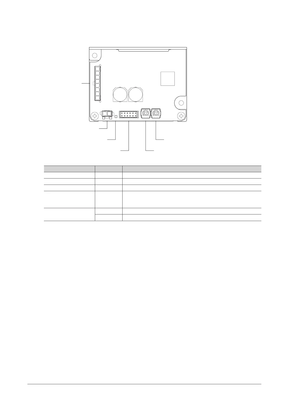
4.5 Names and functions of parts
This section explains the name and function for each part of the driver.
Motor connector
(CN3)
LED (PWR/ALM)
Power supply connector (CN1)
I/O signal connector (CN2)
Internal potentiometer 1 (VR1)
Internal potentiometer 2 (VR2)
CN1 PWR/ALM VR2VR1CN2
+
-
CN3
Name Indication Description
Power supply connector CN1 Connects the power supply cable.
I/O signal connector CN2 Connects the I/O signal cable to connect with an external control device.
Motor connector CN3 Connects the motor cable.
LED PWR/ALM
Lit in green while the power is supplied.
If an alarm is generated, this LED will blink in red. The generated alarm content
can be checked by counting the number of times the LED blinks.
Internal potentiometer
VR1 Sets the rotation speed. (M0 input: ON)
VR2 Sets the acceleration time and deceleration time.
 Loading...