16
Operation
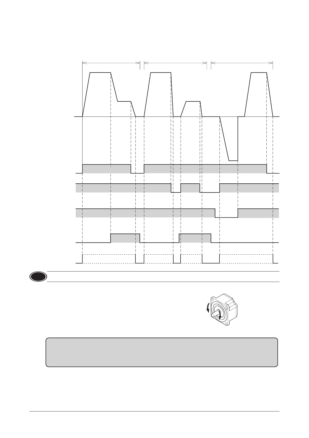
Examples of operation patterns
The gure shows an example when the external potentiometer is set to 2000 r/min and the VR1 is set to 650 r/min.
The rotation direction show the round shaft type. It varies depending on the gear ratio of gearhead.
Switching between two speed levels,
Deceleration stop
2000 r/min
650 r/min
Run, Instantaneous stop Rotation direction switching
ON
OFF
START/STOP
input
FWD/REV
input
RUN/BRAKE
input
M0 input
START
FWD
REV
RUN
RUNRUN
FWD
ON
OFF
ON
OFF
ON
OFF
ON
External analog
setting device
VR1 VR1
External analog
setting device
External analog
setting device
START
CW CW CW CW
CCW
Motor operation
Note
To surely recognize the input signal, ensure the ON time and OFF time of each input signal for at least 10 ms.
7.4 Rotation direction of the motor output shaft
The rotation direction of the motor output shaft represents the direction when
viewed from the motor output shaft.
W
Rotation direction of the gearhead output shaft
The rotation direction of the gearhead output shaft varies depending on the type or the gear ratio of the gearhead.
Check the operating manual supplied with the motor for the rotation direction of the gearhead output shaft.
 Loading...