17
Operation
7.5 Multi-motor control
Operating two or more motors at the same speed can be performed using either an external potentiometer or external
DC voltage.
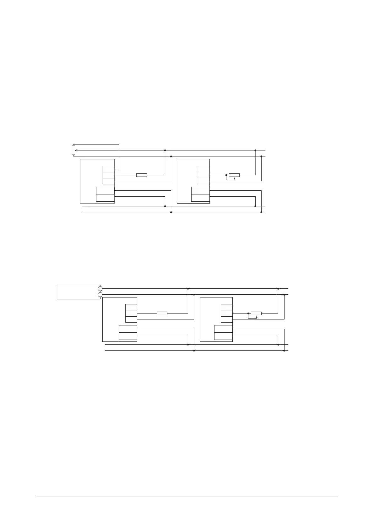
Using an external potentiometer
Use common lines for the power supply and speed setting, and set the speed using VRx as shown in the gure below.
•
Obtain the resistance value for the external speed potentiometer as follows.
Resistance VRx when the number of drivers is n units: VRx (k
Ω
) = 20 k
Ω
/n, permissible dissipation (W) = n/20
Example: If two drivers are connected, 10 k
Ω
and 1/10 W are obtained.
•
For I/O signals other than the speed setting, connect for each driver.
•
If multiple motors are used with speed dierences among them, adjust as follows.
The rst driver: Connect a resistor of 1.5 k
Ω
, 1/20 W to the terminal M on the driver.
The second and subsequent drivers: Connect a variable resistor (VRn) of 5 k
Ω
, 1/20 W to the terminal M on the driver.
•
Keep the number of drivers to 10 units or less in multi-motor control using an external potentiometer.
2
1
Speed setting line
1.5 kΩ, 1/20 W
VRn
5 kΩ, 1/20 W
VH
VM
VL
Driver
Driver
CN2
CN1
+24 V
GND
CN2
CN1
+24 V
GND
VH
VM
VL
Using external DC voltage
•
Use a DC power supply whose current capacity is at least the value calculated by the formula below.
Current capacity (mA) when the number of drivers is n units = 1mA × n
Example: If two drivers are connected, the current capacity should be at least 2 mA.
•
For I/O signals other than the speed setting, connect for each driver.
•
If multiple motors are used with speed dierences among them, adjust as follows.
The rst driver: Connect a resistor of 1.5 k
Ω
, 1/20 W to the terminal M on the driver.
The second and subsequent drivers: Connect a variable resistor (VRn) of 5 k
Ω
, 1/20 W to the terminal M on the driver.
DC power supply
0 to 5 VDC
+
1.5 kΩ, 1/20 W
VRn
5 kΩ, 1/20 W
Power line
Driver
CN2
CN1
+24 V
GND
Driver
CN2
CN1
+24 V
GND
VH
VM
VL
VH
VM
VL
–