Installation
−10−
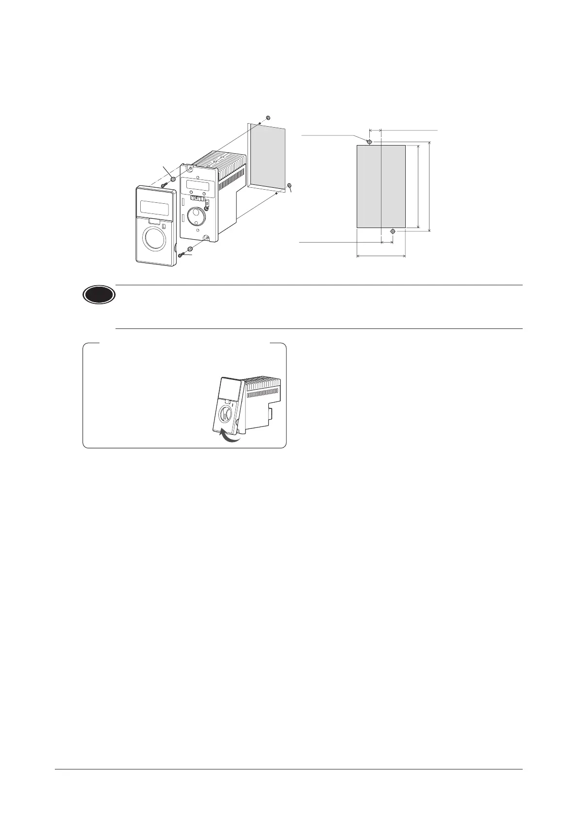
Installation method
Install the driver to a at metal plate oering excellent vibration resistance.
Remove the front panel of the driver and secure the two mounting holes using screws and nuts (M4 or No.8-32UNC: not
supplied). Tighten the screws until no gaps remain between the driver and mounting plate.
115±0.2 (4.53±0.008)
106
+ 1
0
(4.17
+ 0.04
0
)
62
+ 1
0
(2.44
+ 0.04
0
)
15±
0.2 (0.59±0.008)
Screw (M4 or No.8-32UNC: not supplied)
Tightening torque: 0.5 to 0.7 N·m (4.4 to 6.1 lb-in)
• Plate cutout for mounting
Nut
Washer
2×Ø4.5 (Ø0.177)
15±0.2 (0.59±0.008)
Note
•
The space between the mounting hole section and front panel of the driver is 6 mm (0.24 in.).
Therefore, the total height of the screw head and washer should be less than 6 mm (0.24 in.).
The front panel cannot be installed if it is exceeded 6 mm (0.24 in.).
•
If the washer is used, use the washer which outer diameter is Ø10 mm (Ø0.39 in.) or less.
Removing
Remove the front panel having
the under side.
Installing
Install the front panel after placing
on the upper side of the driver
front face.
Removing and installing the front panel
 Loading...