Connection
−16−
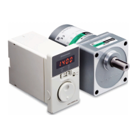
Using a external control equipment with a built-in clamp diode
If a external control equipment with a built-in clamp diode is used,
a leakage path may form and cause the motor to operate even
when the external control equipment power is o, as long as the
driver power is on. Since the power capacity of the controller is
dierent from that of the driver, the motor may operate when the
external control equipment and driver powers are turned on or o
simultaneously.
When powering down, turn o the driver power rst, followed by the
external control equipment power. When powering up, turn on the
external control equipment power rst, followed by the driver power.
Driver
1 to 5
CN4
7
VCC
+5 V
0 V
0 V
equipment
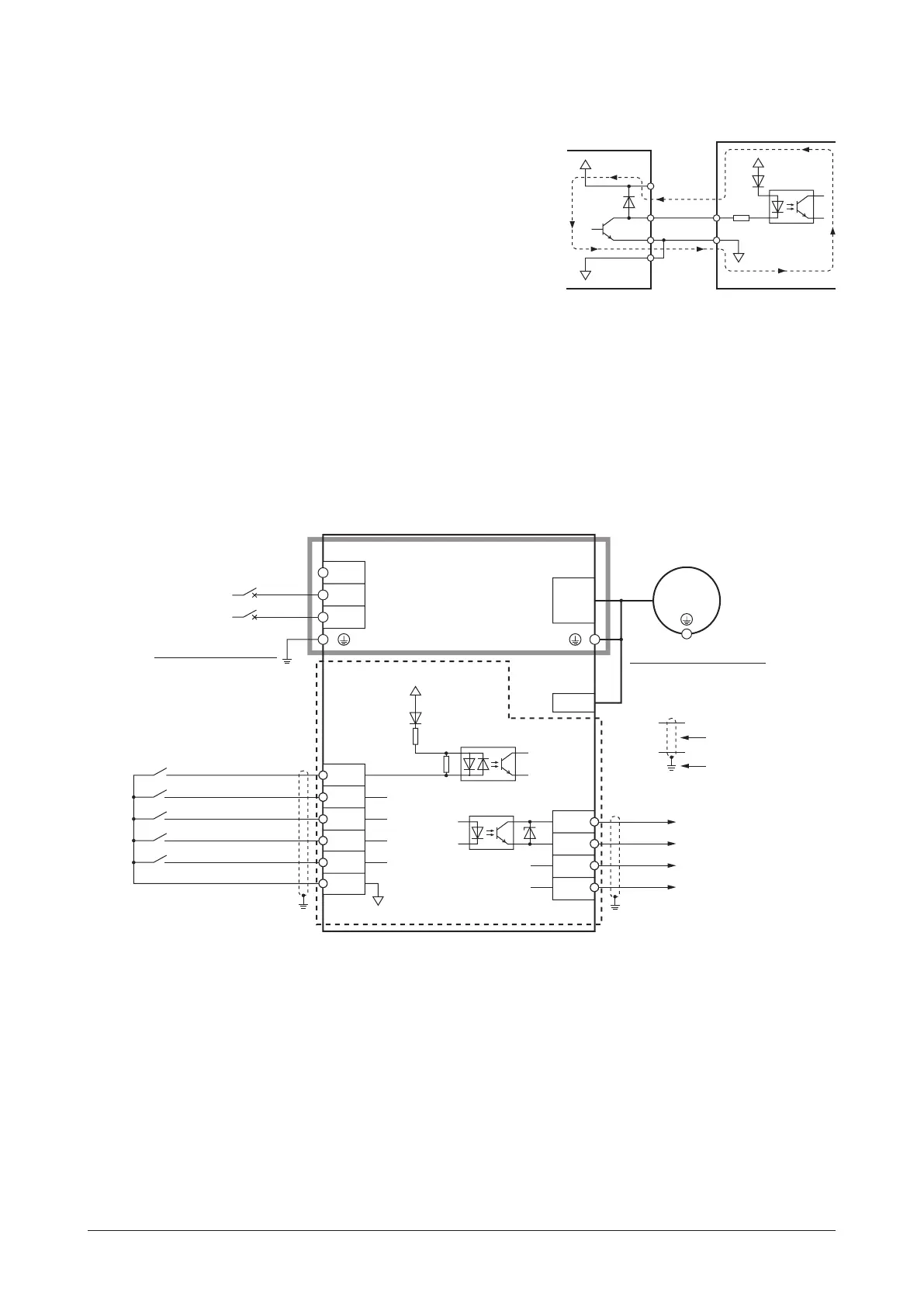
6.5 Connection diagram
Sink logic
The connection example is of the single-phase input. The power supply connection for the three-phase input is dierent.
(6.3 Connecting the power supply
⇒
p.14)
z
When using the built-in power supply
This is a connection example for when the built-in power supply is used for input signals.
The I/O signal in the brackets [ ] is the assignment at the time of shipment.
Motor connection
NC
Motor connector
CN1
CN2
N
L
Motor
Main circuit
Control circuit
CN4
4
7
IN-COM1 (0 V)
5
0 V
N
Circuit breaker
Grounding
820 Ω
IN1 [REV]
IN0 [FWD]
IN2 [M0]
Sensor
connector
CN3
2
3
1
IN3 [M1]
IN4 [ALARM-RESET]
wer supply
connection
L
+5 V
680 Ω
Grounding the driver
Be sure to ground.
Grounding the motor ∗
Be sure to ground.
12
OUT0+
OUT0−
OUT1+
OUT1−
[SPEED-OUT]
[ALARM-OUT1]
11
10
9
CN4
*
Be sure to ground. Refer to "6.2 Grounding" on p.13 for grounding.
Refer to the p.18 for
connection of output signals.
 Loading...