Connection
−18−
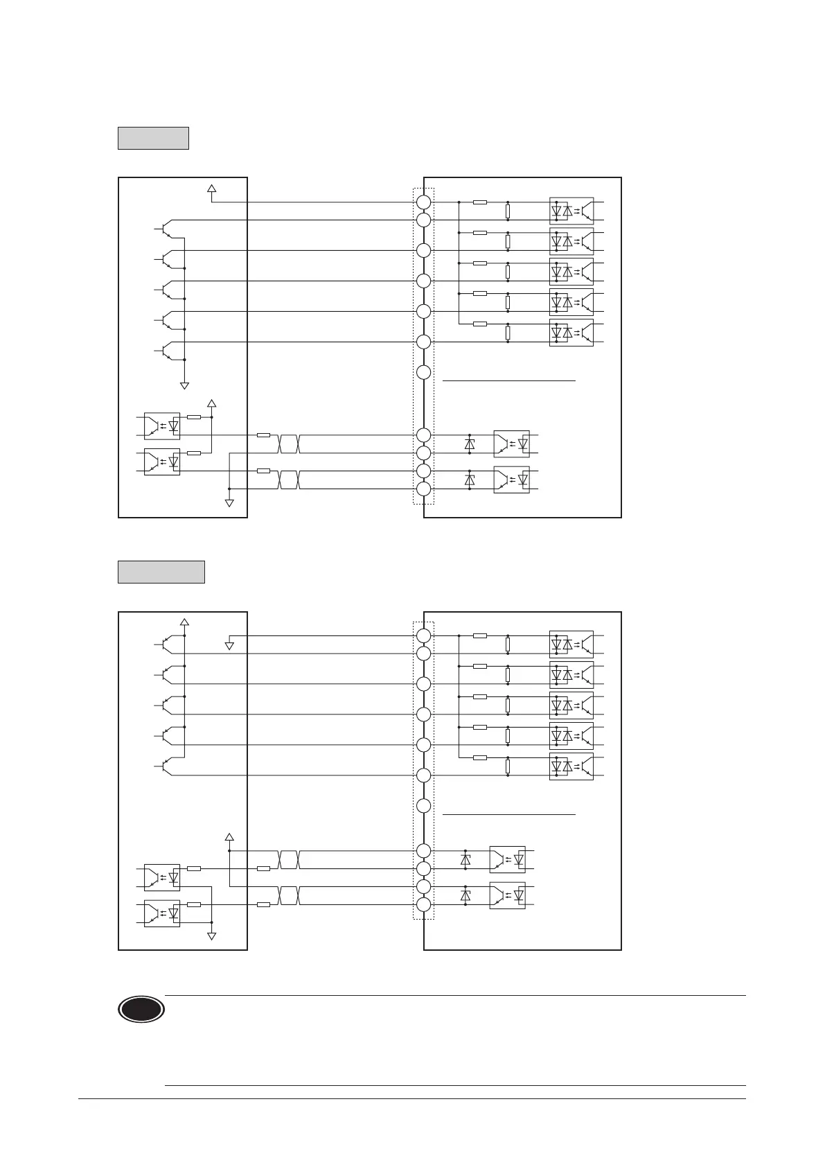
Connection example for I/O signals and programmable controller
This is a connection example when the motor is operated using a transistor output type programmable controller.
Sink logic
24 VDC
CN4
4.5 to 30 VDC
100 mA or less→
IN-COM0
IN0
IN1
IN2
IN3
IN4
IN-COM1
OUT0+
OUT0
-
OUT1+
OUT1
-
100 mA or less→
0 V
5
6
4
3
2
1
6.6 k
6.6 k
6.6 k
6.6 k
6.6 k
820
820
820
820
820
12
R
R
10
11
9
Programmable controller Driver
7
0 V
Recommended resistance value for when the limiting resistor R is connected
In the case of 24 VDC: 680 to 2.7 k (2 W) In the case of 5 VDC: 150 to 560 (0.5 W)
Do not connect anything.
Source logic
24 VDC
CN4
4.5 to 30 VDC
100 mA or less→
100 mA or less→
0 V
5
6
4
3
2
1
6.6 k
6.6 k
6.6 k
6.6 k
6.6 k
820
820
820
820
820
12
R
R
10
11
9
Programmable controller Driver
7
0 V
IN-COM0
IN0
IN1
IN2
IN3
IN4
IN-COM1
OUT0+
OUT0
-
OUT1+
OUT1
-
Recommended resistance value for when the limiting resistor R is connected
In the case of 24 VDC: 680 to 2.7 k (2 W) In the case of 5 VDC: 150 to 560 (0.5 W)
Do not connect anything.
Note
•
Use a power supply of 20.4 VDC to 28.8 VDC, 100 mA or more, for connecting input signals.
•
Turn on the external power supply before turning on the main power supply of the driver.
•
For the OUT0 and OUT1, be sure to connect a current-limiting resistor R so that the current does not exceed
100 mA.When using a programmable controller, check the resistance value inside the controller and connect
a currentlimiting resistor R as necessary.
•
Do not connect anything to the pin No.7 when the external power supply is used.
 Loading...