Connection
−17−
z
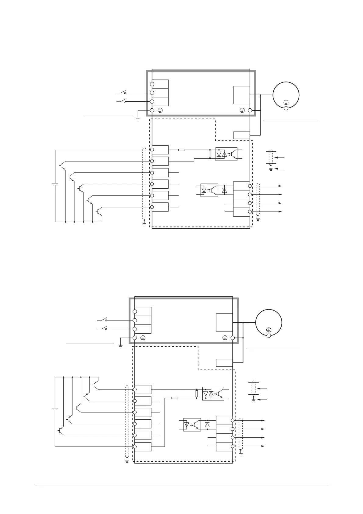
When using the external power supply
This is a connection example for when the external power supply is used for input signals.
The I/O signal in the brackets [ ] is the assignment at the time of shipment.
Connecting input signals
20.4 to 28.8 VDC
100 mA or more
NC
Motor connector
CN1
CN2
N
L
Main circuit
Control circuit
CN4
4
5
N
Circuit breaker
820 Ω
IN1 [REV]
IN0 [FWD]
IN2 [M0]
CN3
2
3
1
IN3 [M1]
IN4
[ALARM-RESET]
Power supply
connection
L
6.6 kΩ
6
IN-COM0
12
OUT0+
OUT0−
OUT1+
OUT1−
[SPEED-OUT]
[ALARM-OUT1]
11
10
9
CN4
Grounding the driver
Be sure to ground.
Motor connection
Motor
Grounding the motor ∗
Be sure to ground.
Sensor
connector
Shielded cable
Grounding
*
Be sure to ground. Refer to "6.2 Grounding" on p.13 for grounding.
Source logic
z
When using the external power supply
This is a connection example for when the external power supply is used for input signals.
The I/O signal in the brackets [ ] is the assignment at the time of shipment.
Connecting input signals
20.4 to 28.8 VDC
100 mA or more
NC
Motor connector
CN1
CN2
N
L
Main circuit
Control circuit
CN4
4
5
820 Ω
IN1 [REV]
IN0 [FWD]
IN2 [M0]
CN3
2
3
1
IN3 [M1]
IN4 [ALARM-RESET]
6.6 kΩ
IN-COM0
6
12
OUT0+
OUT0−
OUT1+
OUT1−
[SPEED-OUT]
[ALARM-OUT1]
11
10
9
CN4
N
Circuit breaker
Power supply
connection
L
Grounding the driver
Be sure to ground.
Motor connection
Motor
Grounding the motor ∗
Be sure to ground.
Shielded cable
Grounding
Sensor
connector
*
Be sure to ground. Refer to "6.2 Grounding" on p.13 for grounding.
Refer to the p.18 for
connection of output signals.
Refer to the p.18 for
connection of output signals.
 Loading...