Connection
−15−
6.4 Connecting the I/O signals
Connect the I/O signals to CN4 on the driver. Refer to p.18 for connection examples with a programmable controller.
Connecting the lead wire
•
Applicable lead wire: AWG24 to 18 (0.2 to 0.75 mm
2
)
•
Length of the insulation cover which can be peeled: 10 mm (0.39 in.)
Crimp terminals can also be used to connect. If crimp terminals are used, select the following terminals.
Manufacturer: PHOENIX CONTACT GmbH & Co. KG
Model: AI 0,25-10 [ Conductor cross-sectional area: 0.14 to 0.34 mm
2
(AWG24) ]
AI 0,34-10 [ Conductor cross-sectional area: 0.14 to 0.34 mm
2
(AWG22) ]
AI 0,5-10 [ Conductor cross-sectional area: 0.40 to 0.65 mm
2
(AWG20) ]
AI 0,75-10 [ Conductor cross-sectional area: 0.65 to 0.82 mm
2
(AWG18) ]
Connector model: DFMC1,5/6-ST-3,5 (PHOENIX CONTACT GmbH & Co. KG)
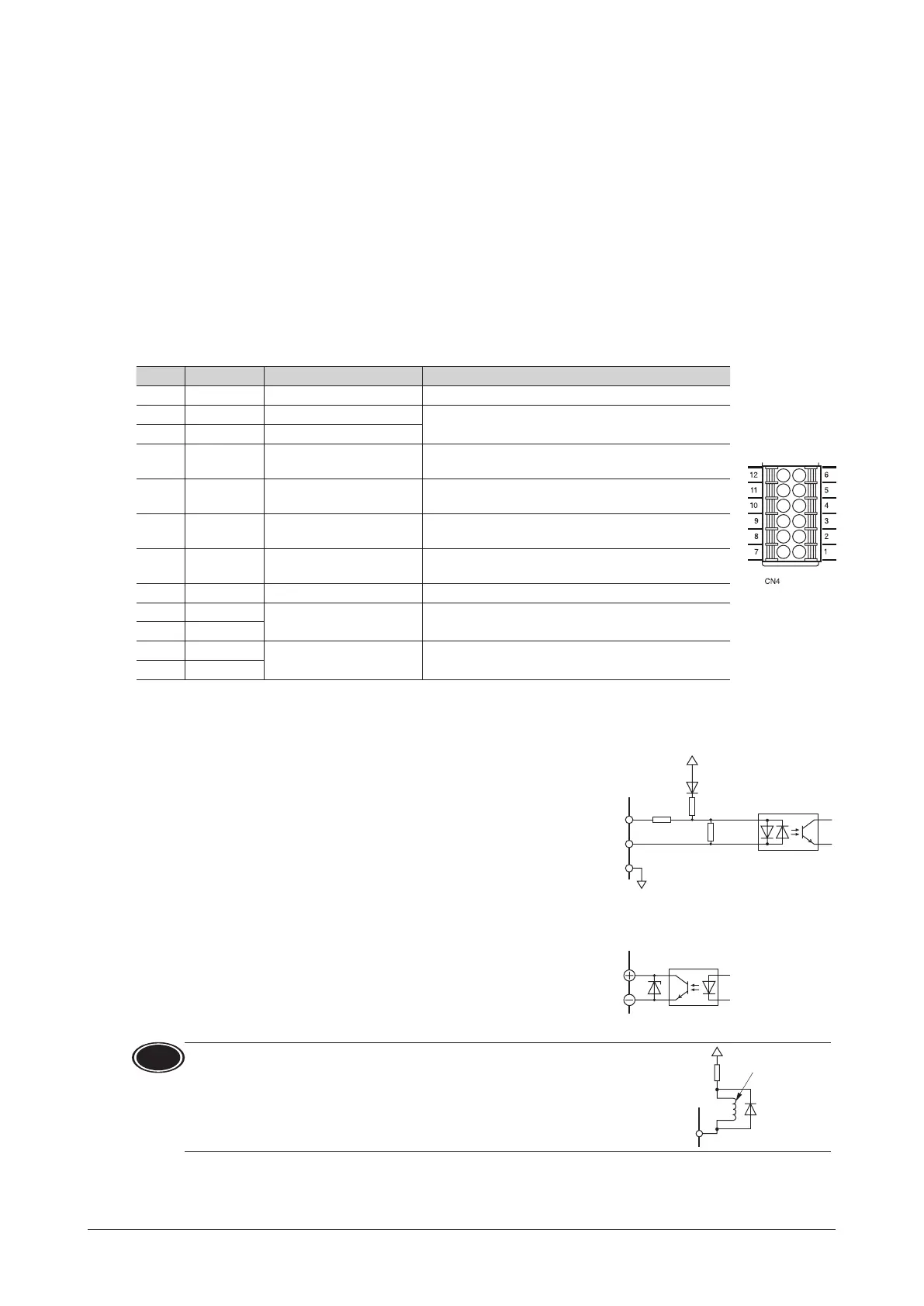
CN4 pin assignment
Pin No. Signal name Function
*
Description
1 IN4 [ALARM-RESET] This signal is used to reset the alarm.
2 IN3 [M1]
This signal is used to select the operation data.
3 IN2 [M0]
4 IN1 [REV]
The motor rotates in the reverse direction while this
signal is being "ON."
5 IN0 [FWD]
The motor rotates in the forward direction while this
signal is being "ON."
6 IN-COM0
Input signal common
(For external power supply)
Connect when using the external power supply.
7 IN-COM1
0 V
(For internal power supply)
Connect when using the built-in power supply.
8 N.C. N.C. Not connected.
9 OUT1−
[ALARM-OUT1]
This signal turns OFF when an alarm generates
(normally closed).
10 OUT1+
11 OUT0−
[SPEED-OUT]
30 pulses are output with each revolution of the motor
output shaft.
12 OUT0+
*
The signal in brackets [ ] is a function that is assigned at the time of shipment. The assigned functions can be changed by
setting parameters. Refer to p.29 for details.
Input signal circuit
All input signals of the driver are photocoupler inputs. Use these signals by
the internal power supply (+5 VDC) or external power supply.
When using the external power supply, both sink input logic and source input
logic can be used by changing the wiring.
Usable external power supply: 24 VDC −15% to +20%, 100 mA or more
820 Ω
6.6 kΩ
7
6
in No.
Photocoupler
1 to 5
680 Ω
Output signal circuit
The driver outputs signals are photocoupler/open-collector output.
When driving each element using the output signal circuit, give consideration
to this ON voltage.
ON voltage: 1.5 VDC maximum
External power supply: 4.5 to 30 VDC, 100 mA or less (For the SPEED-OUT
output, supply at least 5 mA of current.)
9, 11
Note
When connecting a relay (inductive load), etc., to detect alarm outputs,
use a relay with built-in ywheel diode, or provide a y-back voltage
control measure based on diode, etc., for the inductive load.
CN4
in No.10, 12
Induc
Flywheel
diode
 Loading...