Connection
−14−
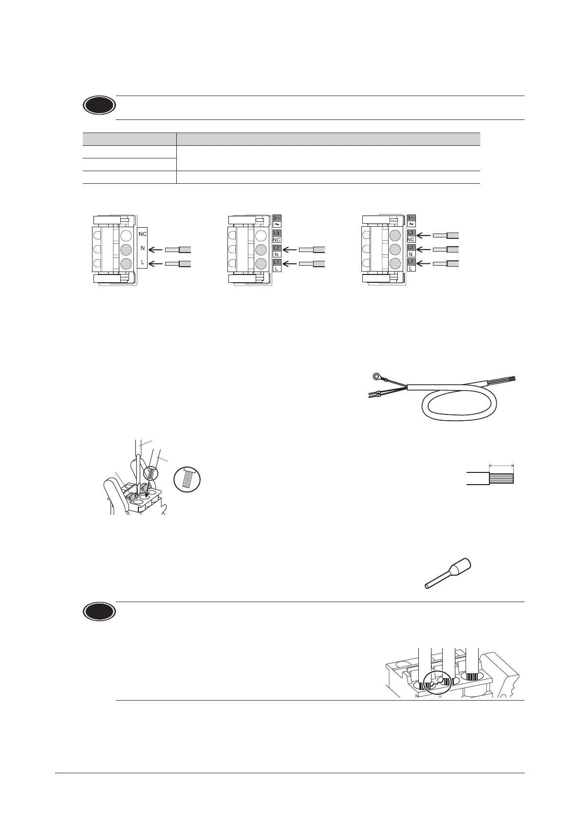
6.3 Connecting the power supply
Connect the power cable to the CN1 on the driver.
Note
Check the specication of the power supply voltage for the driver before applying a voltage.
If a voltage exceeding the rated range is applied, the driver may be damaged.
Input power supply Connecting method
Single-phase 100-120 V
Connect the live side to terminal L, and the neutral side to terminal N.
Single-phase 200-240 V
Three-phase 200-240 V Connect the R, S and T phase lines to the L1, L2 and L3 terminals, respectively.
• Three-phase 200-240 V• Single-phase 200-240 V• Single-phase 100-120 V
The 400 W type is indicated
Connector model: FKC2,5/3-ST-5,08-LR (PHOENIX CONTACT GmbH & Co. KG)
The same driver can be used for single-phase 200-240 V and three-phase 200-240 V.
Connecting terminals vary depending on the power supply voltage used.
Connecting method
The power supply cable is not included.
Power supply cables crimped terminals in advance are provided as accessories
(sold separately). (p.40)
Insert the lead wire while pushing the button of the orange color with a screwdriver.
Lead wire
Wire the lead wire so that
the tip part (copper wires
)
does not become loose.
Button of the
orange color
•
Lead wire size: AWG18 to 14 (0.75 to 2.0 mm
2
)
•
Length of the insulation cover which can be peeled:
10 mm (0.39 in.)
•
Conductive material: Use only copper wire.
Crimp terminals can also be used to connect.
If crimp terminals are used, select the following terminals.
Manufacturer: PHOENIX CONTACT GmbH & Co. KG
Mode:l AI 0,75-10 [ Conductor cross-sectional area: 0.65 to 0.82 mm
2
(AWG18) ]
AI 1-10 [ Conductor cross-sectional area: 0.82 to 1.2 mm
2
(AWG18) ]
AI 1,5-10 [ Conductor cross-sectional area: 1.25 to 1.8 mm
2
(AWG16) ]
AI 2,5-10 [ Conductor cross-sectional area: 2.0 to 3.0 mm
2
(AWG14) ]
Note
•
When cycling the power or plugging/unplugging the connector, turn o the power and wait for 1 minute or more
before doing so.
•
Ensure that the connector plugged in securely. Insecure connections may cause malfunction or damage to the
product.
•
Insert the lead wire to the connector so that the tip part (copper
wires after stripping the insulation cover) does not become loose.
The loose tip part (copper wires) may cause short-circuiting, leading
to damage to the product.
Circuit breaker
Be sure to connect a circuit breaker to the power line of the driver to protect the primary circuit.
Rated current of protective device: Single-phase input 10 A, three-phase input 10 A
Circuit breaker: Mitsubishi Electric Corporation NF30
 Loading...