4 Reference & Installation Manual
2.0 Installation
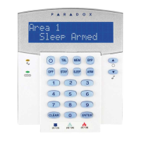
The LCD keypad (DG2P-641) is connected to the control panel's
communication bus in a star and/or daisy chain configuration.
The 4-wire communication bus provides power and two-way
communication between the control panel and all modules
connected to it. Connect the four terminals labeled red, black,
green and yellow of each keypad to the corresponding terminals
on the control panel (refer to Figure 2.1 on page 5). Refer to the
Digiplex or DigiplexNE Reference & Installation Manual f or the
maximum allowable installation distance from the control panel.
2.1 Connecting Keypad Zones
Each keypad has one traditional hardwired input terminal,
allowing you to connect one detector or door contact directly to
the keypad. For example, a door contact located at the entry
point of an establishment can be wired directly to the input
terminal of the entry point keypad instead of wiring the door
contact all the way to the control panel.
Connect the device to the keypad's input terminal as shown in
Figure 2.1 on page 5. In order to communicate its status to the
control panel, devices connected to the keypad's input terminal
must be assigned to a zone in the control panel and the zone's
parameters must be defined. For more information on zone
assignment, please refer to the Digiplex or DigiplexNE
Reference & Installation Manual. Please note that even with the
ATZ (zone doubling) feature enabled, the keypad supports only
one detection device.
 Loading...