14
DB Series Nitrogen Generator DB5-20 Model
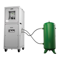
3.2 Nitrogen Generator Connections
1) AIR INLET – Will be marked on the nitrogen generator with a label. Ensure inlet air quality meets
guidelines specified in this user manual.
2) NITROGEN OUTLET – Connect to product/process requiring nitrogen. It is recommended that a
block and vent valve be installed to isolate the nitrogen generator from the process to manually vent
nitrogen to atmosphere during initial startup and troubleshooting.
3) NITROGEN OUTLET TO BUFFER TANK – Connect generator to manual isolation valve (MIV 101)
on nitrogen buffer tank (NST 101).
4) NITROGEN INLET FROM BUFFER TANK – Connect generator to manual isolation valve (MIV 102)
on nitrogen buffer tank (NST 101).
5) POWER SUPPLY – Use power cable provided. Verify voltage and frequency of power supply
matches the nitrogen generator design stated on the serial label.
3.3 Operator Interface Definitions
The cycling of the PSA nitrogen gas generation system is controlled by a programmable logic
controller (PLC), which sends electrical signals to solenoid valves. The solenoid valves pneumatically
actuate the process valves, which control air and nitrogen flow. The operator interface consists of
the following. An overview of the interface is shown in Section 3.4 "Operator Interface Overview."
1) ON/OFF SWITCH (SS 1) – Turns the generator cycle on and off.
2) HUMAN MACHINE INTERFACE (HMI) – LCD display provides pertinent operations data including
running status, oxygen content, nitrogen flow rate, nitrogen pressure, Eco % (time in standby), time
cycle (generating / equalization) and run hours.
3) TACTILE KEYPAD – Function, navigation, ESC and OK keys for operator input.
4) USB PORT – Allows for exporting historical sensor data and alarm log.
5) OPERATING PRESSURE GAUGE (PI 101) – Provides operating pressure of online vessel(s).
6) OUTLET NITROGEN PRESSURE GAUGE (PI 102) – Provides nitrogen pressure at the outlet
of the generator.
7) OUTLET PRESSURE REGULATOR (PRV 101) – Allows for on-site adjustment of outlet
nitrogen pressure.
8) PRODUCT CONTROL VALVE (PCV 101) – Allows for on-site adjustment of outlet nitrogen flow.
Reference Section 3.1 “Equipment Overview” for location of connections. All connections
must be made prior to startup and should be properly rated for minimum/maximum oper-
ating conditions of the system. Only competent personnel trained, qualified, and approved
by Parker should perform installation, commissioning, service, and repair procedures.
WARNING