28
DB Series Nitrogen Generator DB5-20 Model
5. Communications
Ethernet Communications – DB 5-20 generators come standard with an Ethernet Modbus TCP/IP
interface located along the bottom edge of the controller. The port comes preconfigured in DHCP
mode. The MAC address is located on the front of the controller located inside the control box and
can be used to map the controller to a static IP address within the DHCP server. Modbus-RTU is
available using a separate gateway device.
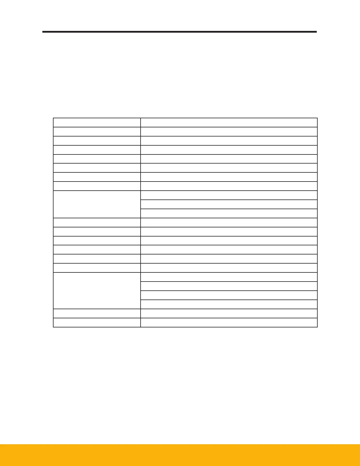
5.1 MODBUS Register Map
Register Address Description
00001 Unit is running
00002 Unit in Standby
00003 Unit left tower is generating
00004 Unit right tower is generating
00005 Unit tower pressures are equalizing
00006 Relay #1 contacts are closed
00007 Relay #2 contacts are closed
00008
Oxygen Probe range.
0 = 0.01 to 25.00 percent.
1 = 0 to 1000 ppm
00009 Unit has shut-down due to an alarm
00010 High Oxygen Alarm
00011 High Oxygen Warning
00012 Oxygen Sensor input fault alarm
00013 Flow sensor input fault alarm
00014 Pressure sensor input fault alarm
30001
Oxygen Purity
See register 00008 for sensor range
0 = 0 to 2500, Divide by 100 to calculate percentage
1 = 0 to 1000 ppm
30002 NST Flow – range depends on model
30003 NST Pressure – 0 to 200 psi
 Loading...