Mechanical Instructions
EN 11DVDR615/69 4.
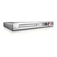
4.2.3 Dismantling the Tray
– Remove the encasing as described in 4.2.2
– Disengage the two holders that fix the tray [1] and pull out
the tray [2]
Figure 4-8 Remove Tray
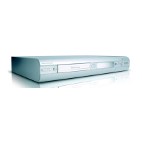
4.2.4 DVD-M (Drive Mechanism)
Caution: Never try to align or repair the DVD-Module itself!
Only the factory can do this properly. Service engineers are
only allowed to exchange the sledge motor assy.
After Exchanging the DVD-M (or the PCB) the complete drive
has to be adjusted! Refer to chapter 8 for adjustment
instructions!
– Remove encasing and FEBE board as described in 4.2.2
– Remove the Sealing strip 5 by uncatching it
– Loosen the 4 screws/washer [1] to remove the DVD-M [2]
Figure 4-9 Remove DVD-M
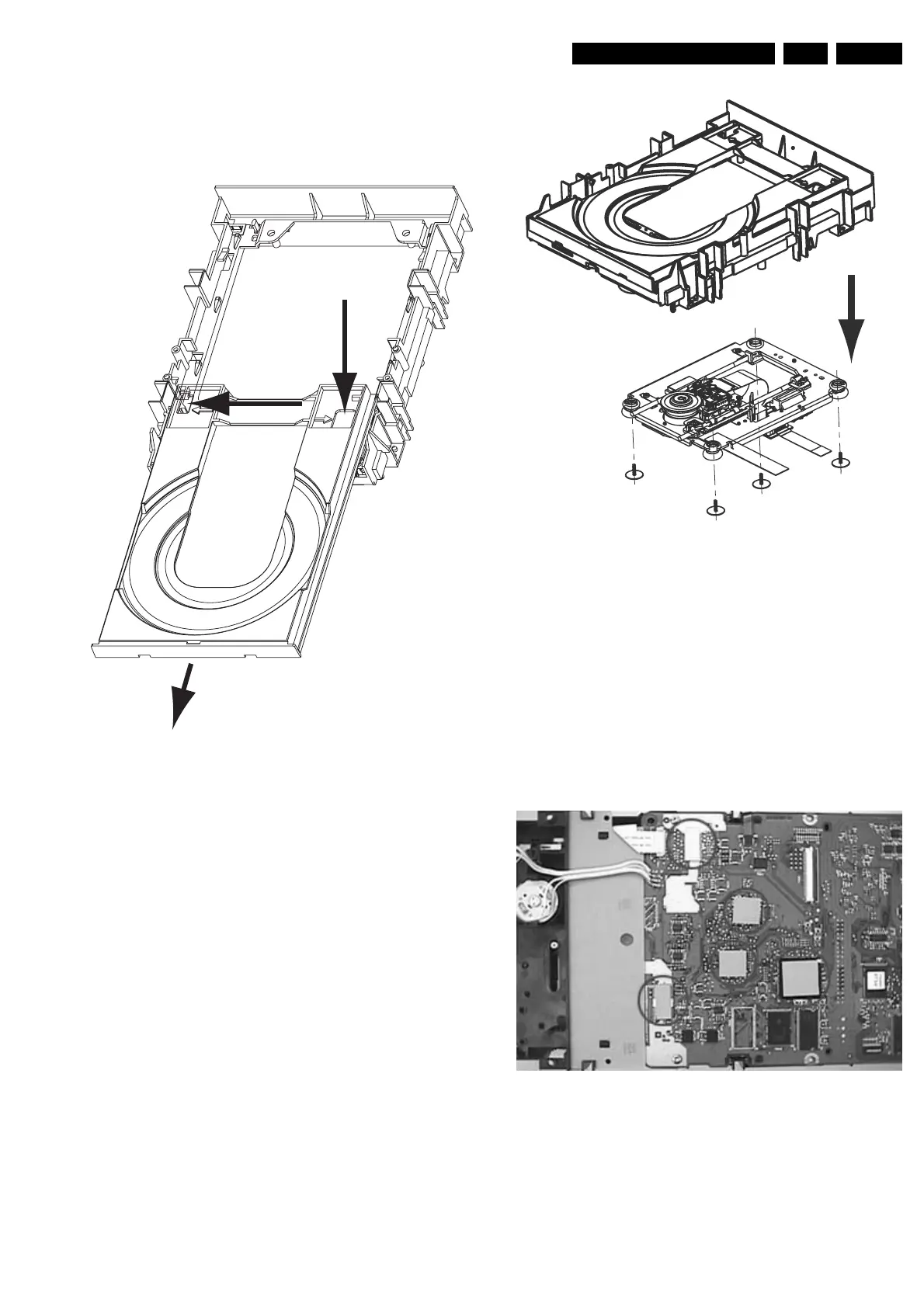
4.2.5 Re - assembly
To re-assemble the module, do all processes in reverse order.
Take care of the following:
• Heat Paths:Put the 5 heat paths (gray rubber pieces) back
to their position on the ICs.
• Complete module: Place all wires/cables in their original
positions
• Emergency opening slot: Be sure that the slot for the
emergency tray opener is covered by adhesive tape!
Figure 4-10 Heat Paths
1
1
2
2
1
1
1
1
http://www.jdwxzlw.com/?fromuser=华盛维修
 Loading...