Mechanical Instructions
EN 9DVDR615/69 4.
4. Mechanical Instructions
4.1 Dismantling and Assembly of the Set
For item numbers please see the exploded views in chapter 10.
4.1.1 Front Panel Assembly
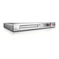
– After removing the top cover, remove tray front 134+138,
see picture 4-1
– Remove the three screws 188
– Release the two snap hooks on the sides and remove the
front assembly
– Remove the 4 screws 186 to remove the front plate 184,
see picture 4-2
Figure 4-1
Figure 4-2
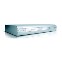
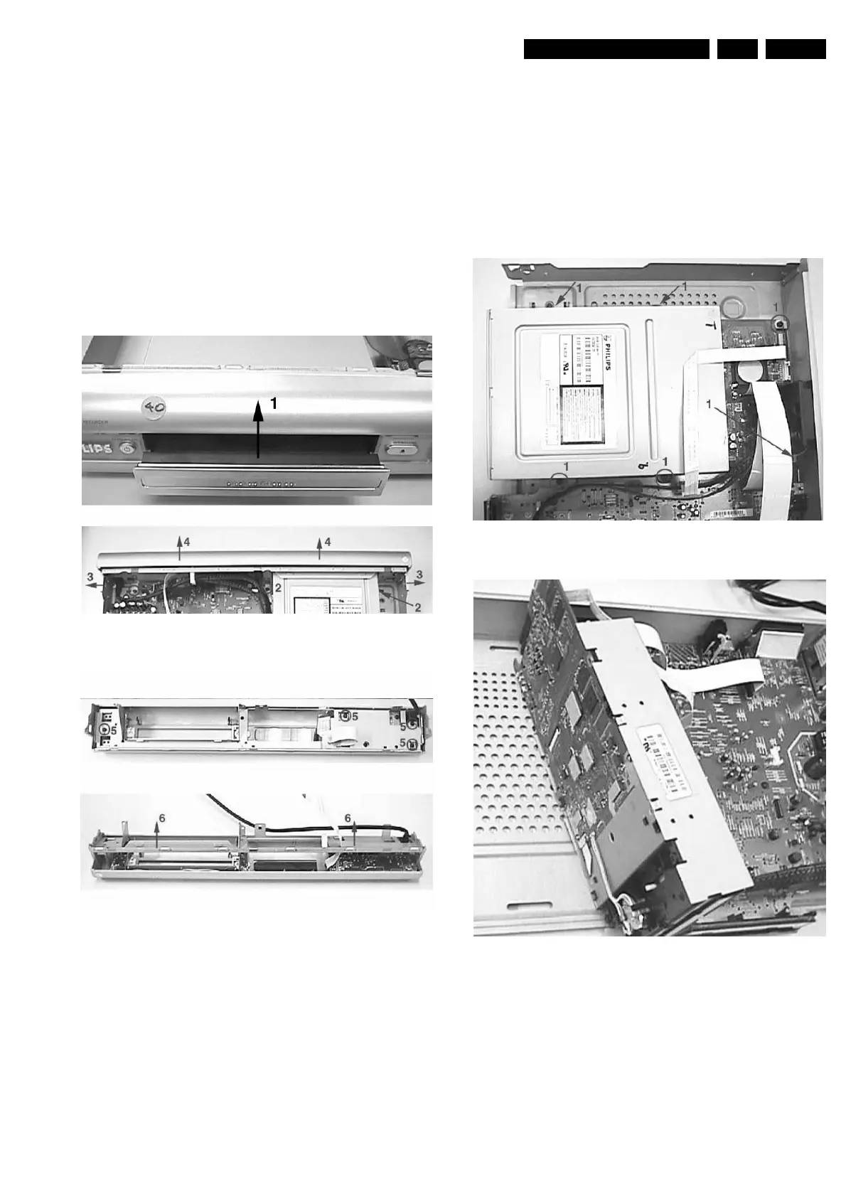
4.1.2 Basic Engine VAU8041
– Remove the Front Panel Assembly as given in 4.1.1
– Remove the 6 screws 260, 269 to free the Basic Engine
– Remove the dust cover assembly 147 and 148
– Loosen 2 screws to remove bracket 256
– Loosen 4 screws to remove the Basic Engine metal casing
– Place the Basic Engine in the service position
Figure 4-3
Figure 4-4
http://www.jdwxzlw.com/?fromuser=华盛维修
 Loading...