5.23
BODY / STEERING / SUSPENSION
5
REAR A-ARMS
Removal
The following procedure details upper and lower A-arm
removal and replacement on one side of the vehicle. Repeat the
following steps to remove the A-arm(s) from the opposite side.
NOTE: Use the exploded view in this section as a
reference during the procedure (see page 5.25).
1. Elevate and safely support the rear of the vehicle off the
ground.
2. Remove the wheel nuts, and rear wheel.
Upper A-arm Removal
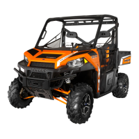
1. Remove the fastener (A) attaching the upper A-arm to the
bearing carrier.
2. Remove the fastener (B) attaching the upper A-arm to the
frame and remove the upper A-arm from the vehicle.
3. Examine A-arm and bearing carrier bushings and pivot
tubes (see “Exploded View” on page 5.25). Replace if
worn. Discard hardware.
4. If not replacing the A-arm, thoroughly clean the a-arm and
pivot tubes.
5. Insert new A-arm bushings and pivot tubes into new A-arm.
Lower A-arm Removal (RZR)
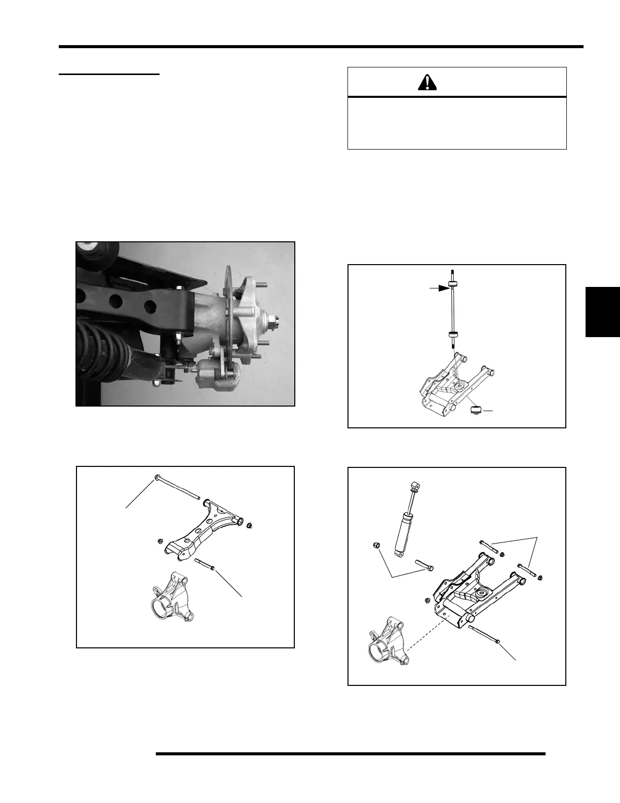
1. While holding the stabilizer bar linkage, remove the lower
nut retaining the linkage to the lower A-arm.
2. Remove the fastener (C) retaining the lower portion of the
shock to the lower A-arm.
3. Remove the fastener (D) attaching the lower A-arm to the
bearing carrier.
A
B
Standard RZR
Shown
WARNING
The locking agent on the existing bolts was
destroyed during removal. DO NOT reuse old
hardware. Serious injury or death could result if
fasteners come loose during operation.
Hold HERE with
open-end wrench
Remove lower
linkage nut
C
D
E

 Loading...