10.19
ELECTRICAL
10
RELAYS
Operation
Located in the fuse box under the dash, the relays assist with
component operation like the fan, fuel pump, and EFI system.
The fan relay, controlled by the ECU and Temp Sensor, operates
the fan.
The EFI relay, controlled by the ECU, turns on power for
components such as the fuel pump, injectors, and ignition coils.
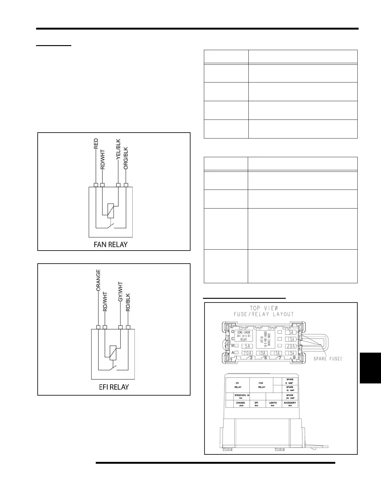
FUSE BOX LAYOUT
FAN RELAY
COLOR FUNCTION
Red / White
Key-On battery power supply, switched on
by key switch, enables power to relay.
Orange / Black
Fused 20-Amp power, switched by relay,
provides power to Fan Motor.
Yellow / Black
ECU input to connect relay Fused 20-Amp
power to Fan Motor output.
Red
Fused 20-Amp, constant battery power IN
supply for EFI component operation.
EFI RELAY
COLOR FUNCTION
Orange
Fused 15-amp, constant battery power IN
supply for EFI component operation.
Red / White
Key-On battery power supply, switched on
by key switch, enables power to relay.
Red / Black
EFI power output. Switched by relay when
ECU sends a signal on the GRY/W wire,
closing the relay. Supplies 15-amp power
for ECU-controlled operation of EFI
components.
Gray / White
ECU input to enable relay. The ECU
supplies a ground which closes the relay,
supplying power to run the fuel pump,
injectors, etc.
Located under
the dash

 Loading...