5.24
BODY / STEERING / SUSPENSION
4. Remove the (2) fasteners (E) attaching the lower A-arm to
the frame and remove the lower A-arm from the vehicle
(see previous illustration).
5. Examine A-arm and bearing carrier bushings and pivot
tubes (see “Exploded View”). Replace if worn. Discard
hardware.
6. If not replacing the A-arm, thoroughly clean the a-arm and
pivot tubes.
7. Insert new A-arm bushings and pivot tubes into the new
A-arm.
Lower A-arm Removal (RZR “S”)
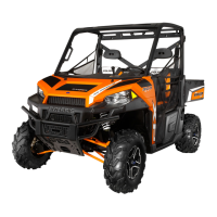
1. Remove the lower fastener (F) retaining the stabilizer bar
linkage to the lower A-arm.
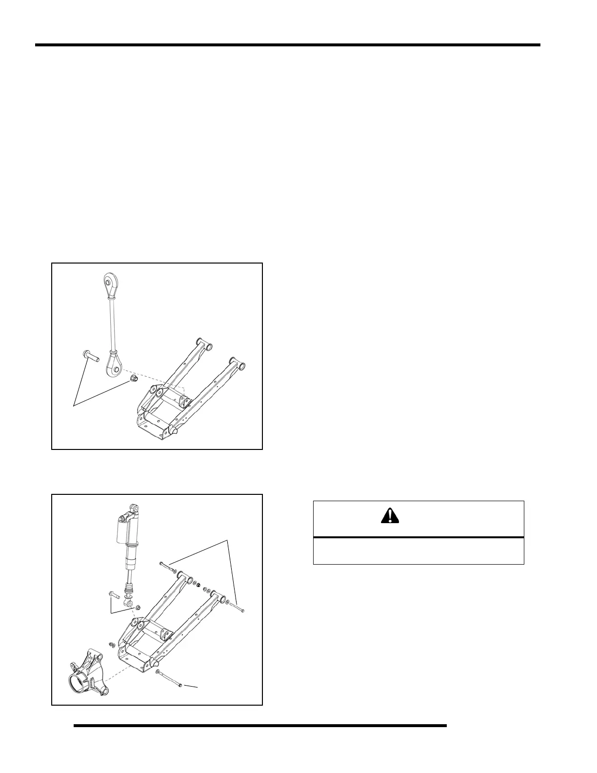
2. Remove the fastener (G) retaining the lower portion of the
shock to the lower A-arm.
3. Remove the fastener (H) attaching the lower A-arm to the
bearing carrier (see previous illustration).
4. Remove the (2) fasteners (J) attaching the lower A-arm to
the frame and remove the lower A-arm from the vehicle
(see previous illustration).
5. Examine A-arm and bearing carrier bushings and pivot
tubes (see “Exploded View”). Replace if worn. Discard
hardware.
6. If not replacing the A-arm, thoroughly clean the a-arm and
pivot tubes.
7. Insert new A-arm bushings and pivot tubes into the new
A-arm.
Installation
1. Install lower A-arm assembly onto vehicle frame. Torque
new fasteners to 33 ft. lbs. (45 Nm).
2. Attach lower A-arm to bearing carrier. Torque new
fastener to 38 ft. lbs. (52 Nm).
3. Route brake line on top of the lower A-arm and between
lower shock mounting tabs.
4. Reinstall the lower portion of the shock to the lower A-arm.
Torque shock fastener to 27-33 ft. lbs. (37-45 Nm).
5. Install upper A-arm assembly onto vehicle frame. Torque
new fastener to 33 ft. lbs. (45 Nm).
6. Attach upper A-arm to bearing carrier. Torque new
fastener to 33 ft. lbs. (45 Nm).
7. Install wheel and torque wheel nuts to specification.
F
G
H
J
WARNING
Upon A-arm installation completion, test vehicle
at low speeds before putting into service.

 Loading...