PROPULSION
6.112004 Four Stroke PWC Service Manual
W ARNING
Before working on the drive system, be sure the lanyard cord and lock plate are removed from the engine stop
switch to kill the ignition or severe injury could result.
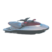
Impeller Clearance
1. Remove lanyard cord and lock plate from engine
stop switch. Disconnect battery ground (--) cable.
2. Remove intake grate and check impeller to housing
clearance with a feeler gauge. Measure clearance
at leading edge, middle, and trailing edge of each
blade. Replace impeller if clearance exceeds
service limit at any point. If clearance exceeds
service limit with a new impeller, replace pump
housing.
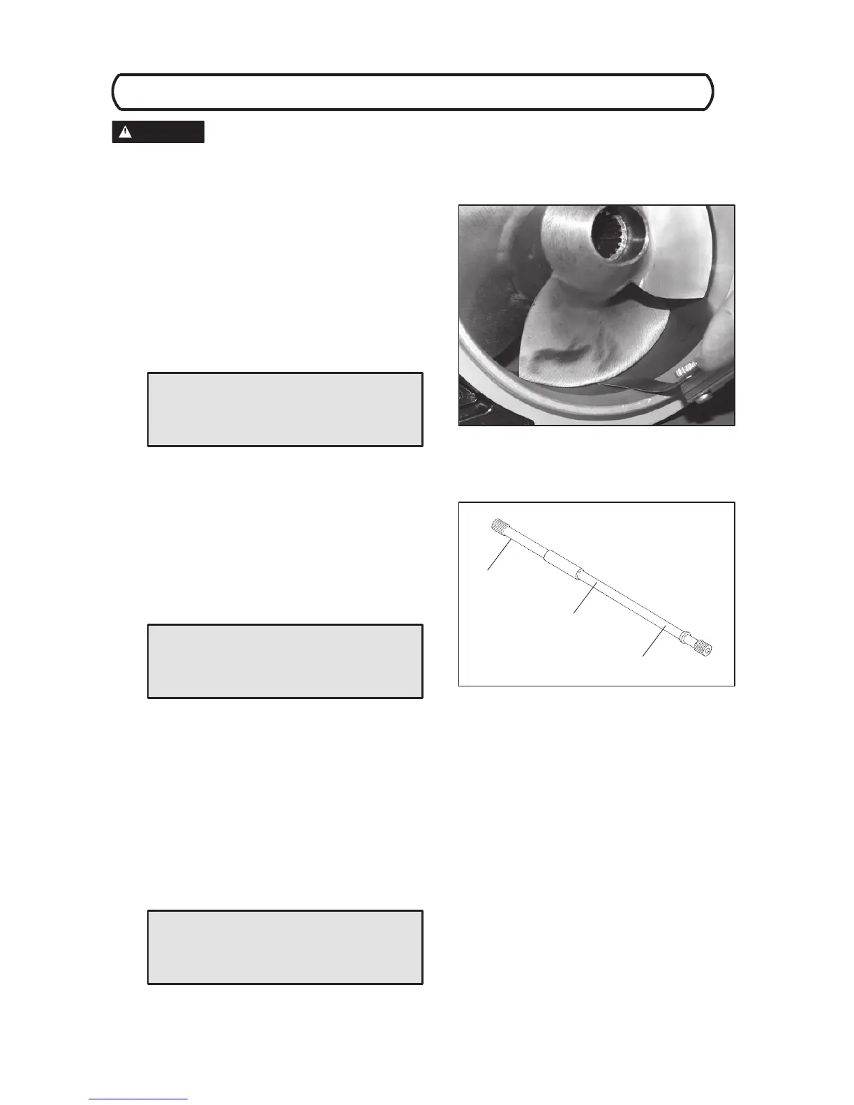
Drive Shaft Inspection
1. Clean driveshaft and support in V - blocks as shown
(C). Measure runout by rotating shaft and
observing dial indicator at point (B). Replace if
runout exceeds the service limit.
NOTE: Excessive driveshaft runout can cause vibra-
tion, bearing, and spline failure. See Pump/Final Drive
T roubleshooting at the end of chapter 2.
2. Inspect driveshaft splines and threads inside
engine drive coupler and impeller carefully for wear
or damage. Replace worn parts. Rubber bumpers
control driveshaft end play. Replace if worn,
cracked or damaged.
NOTE: If driveshaft, impeller, or coupler threads are
worn or damaged, improper pump-to-hull, or pump-to-
engine alignment should be suspected. Refer to Pump/
Drive shaft Alignment on pages 5.13 -- 5.14 for more in-
form a ti o n .
Impeller Clearance
Std: .002 - .008″ (.05 - .20 mm)
Service Limit: .020″ (.5 mm)
C
B
C
Place dial indicator
at (B)
Support in V -blocks
at (C)
Drive Shaft Runout
Service Limit: .005″ (.13mm)
Drive Shaft End Play
.100-.200″ (2.54-5.08mm)
 Loading...