ENGINE DISASSEMBLY / ASSEMBLY
4.132004 Four Stroke PWC Service Manual
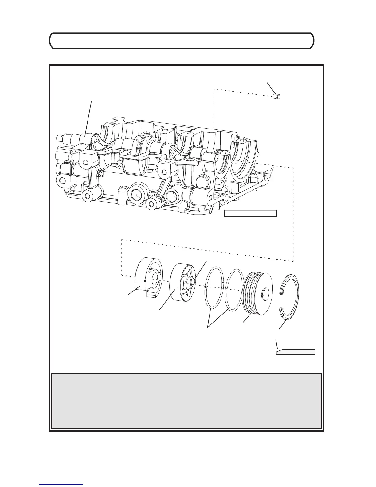
HIGH PRESSURE OIL PUMP ASSEMBLY
ASSEMBLY NOTES
UseLIBERAL amounts of engine oil on timing rotor, inner and outer rotors, I.D. of retaining cap, and retaining cap o--rings during
oil pump assembly.
Snap ring chamfer must face outwards, towards rear of engine when installed.
Verify retaining cap does not move when snap ring is installed.
An audible “click” must be heard and alignment pin must be inserted properly into engine case when installing the timing rotor into the
oil pump bore.
Verify balance shaft timing key is oriented properly inside shaft keyway.
SNAP RING
(CHAMFER FACES OUT)
RETAINING CAP
O--RINGS
OUTER ROTOR
INNER ROTOR
TIMING ROTOR
BALANCE SHAFT TIMING KEY
BALANCE SHAFT
PTO--END OF ENGINE
 Loading...