VALVE CLEARANCE SPECIFICATION
INTAKE VALVE: .08 -- .15MM (.003 -- .006)
EXHAUST VALVE: .18 -- .25MM (.007 -- 0.10)
MAINTENANCE
2.8
2004 Four Stroke PWC Service Manual
E.S.P. Function Testing
1. Watercraft must be on engine stand or on trailer to perform test.
2. Insert lanyard into stop switch. Start engine.
NOTE: Severe engine damage may occur if engine is run more than 30 seconds without supplying
water to the freshwater cooling circuit.
3. Using shop air, spin the paddle wheel located in the rear of the ride plate. Enough air must be directed at the
paddle wheel to generate a speed reading on the gauge above 15 MPH.
4. With the indicated vehicle speed above 15 MPH, quickly turn the handlebars either to the full left or full right
position.
When the procedure is performed, the engine idle should rise above 1400 -- 1500 RPM.
Valve Clearance Adjustment Procedure
NOTE: Always perform procedure when the engine is cold.
Adjusting the valve clearance can be accomplished while the engine is inside the engine compartment.
1. Remove the ignition coils, spark plugs, fuel injector
wiring harness, and cam phase sensor harness
connector from the valve cover.
2. Remove the valve cover from the engine.
3. Insert the lanyard into the stop switch. Rapidly tap the
start button to rotate the engine.
4. Rotate the engine until the MAG cylinder is at TDC --
COMPRESSION stroke.
NOTE: TDC -- COMPRESSION stroke is found when
the both cam lobes are pointed down, away from
the rocker arms, and the piston is at TDC.
5. Verify each rocker arm is loose and not engaged by
the camshaft.
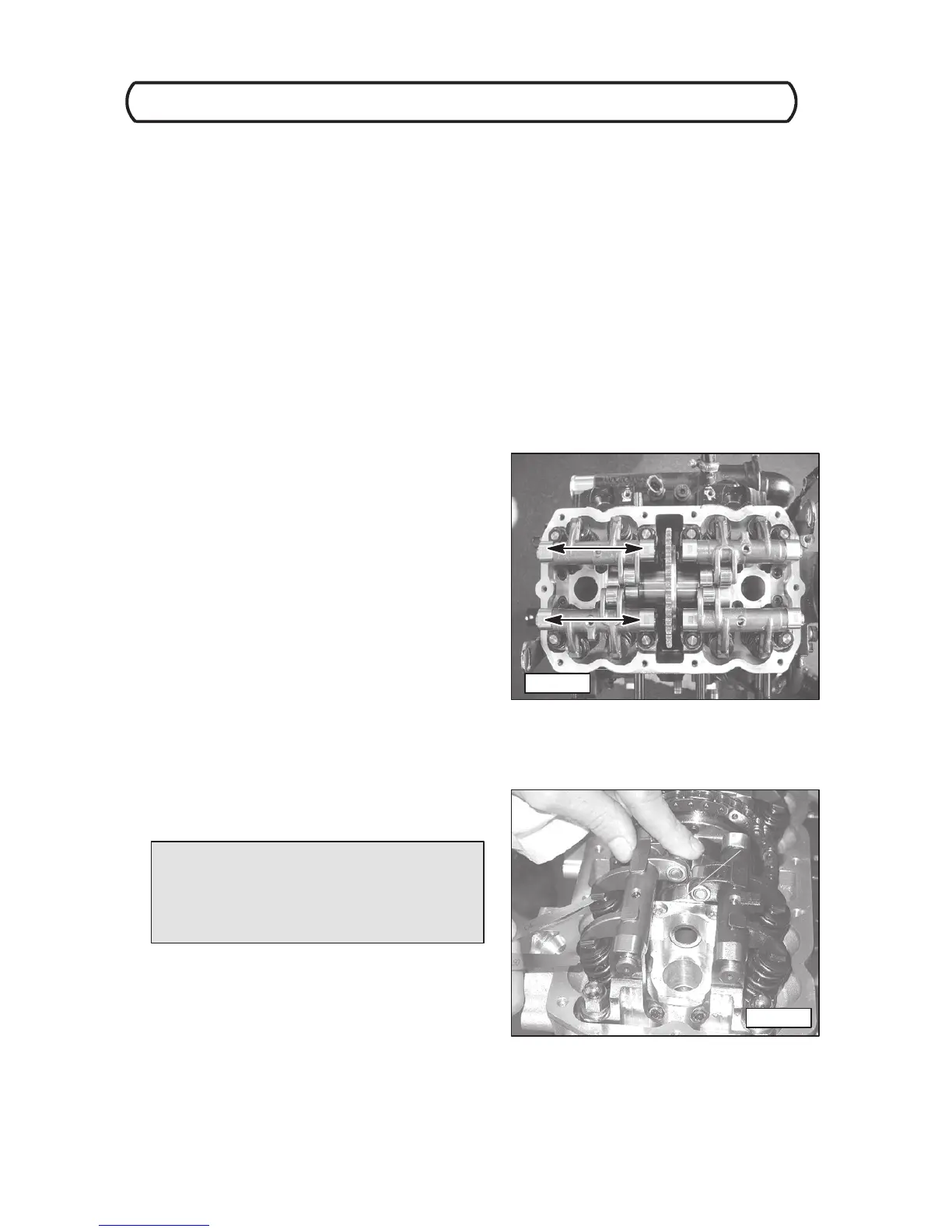
6. Using a feeler gauge, measure the clearance at each
of the 4 valves between the installed shim and rocker
arm. Record each measurement. (Photo B)
7. If the measured clearance is within specification, no
adjustment is required.
8. If the measured clearance is out of specification, the
valve shim must be replaced with one that will satisfy
the clearance specifications.
Photo A
Photo B
 Loading...